Analyzer, and analysis method

A technology of analysis device, analysis method, applied in the field of analysis program

Inactive Publication Date: 2013-03-06
FUJITSU LTD
View PDF5 Cites 0 Cited by
  • Summary
  • Abstract
  • Description
  • Claims
  • Application Information

AI Technical Summary

Problems solved by technology

However, it is difficult to sufficiently suppress warping that occurs during mounting

Method used


Image

  • Analyzer, and analysis method
  • Analyzer, and analysis method
  • Analyzer, and analysis method

Examples


Embodiment Construction

[0036] Hereinafter, embodiments of the present invention will be described in detail with reference to the drawings. The structural analysis device according to the embodiment of the present invention is a device that performs structural analysis of a printed wiring board or the like. That is, the object (analysis object) for which the structure analysis device performs structure analysis is a printed wiring board or the like.

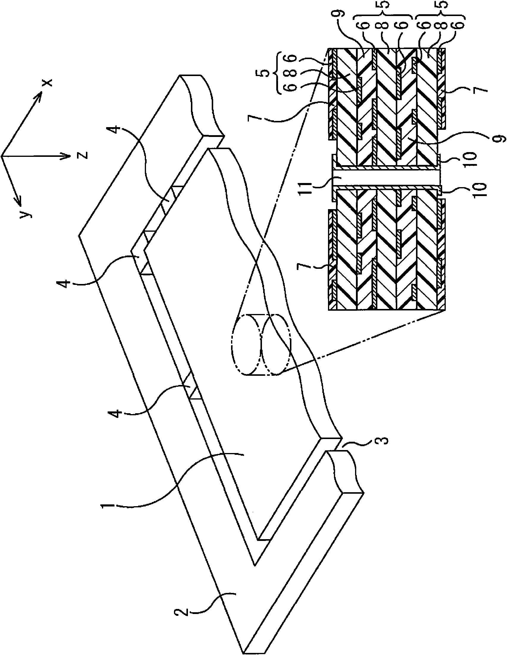
[0037] First, the analysis target will be explained. figure 1 It is a diagram showing an example of an analysis target of the structure analysis device according to the embodiment of the present invention.

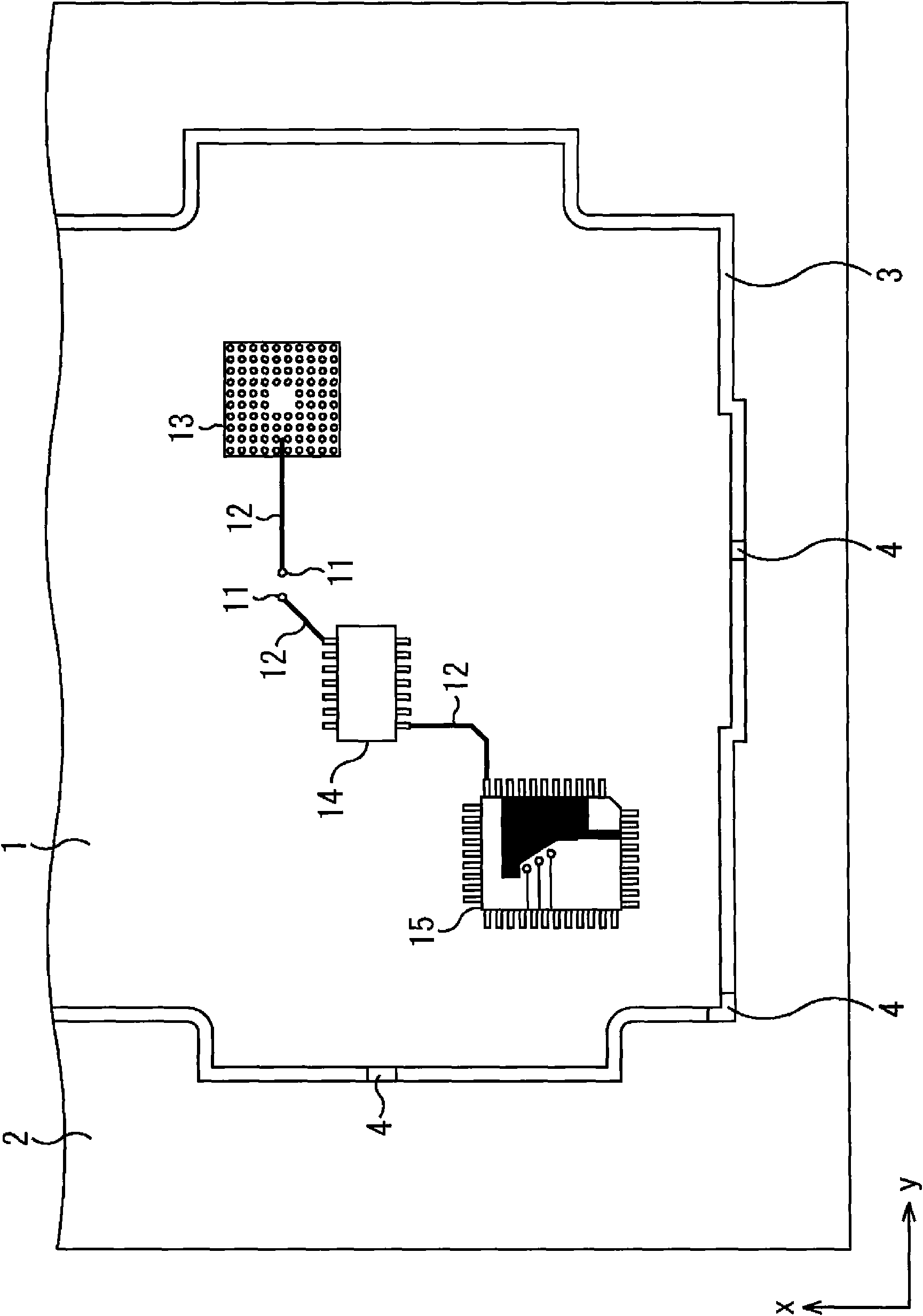
[0038] In this example, the analysis target includes a printed wiring board 1 and a frame 2 surrounding the printed circuit board 1. There is a separation groove 3 between the printed wiring board 1 and the frame 2, and ribs 4 for connecting the printed wiring board 1 and the frame 2 are provided in multiple places of the separation groove 3. By cutt...


PUM


Abstract

A first generation portion divides an object to be analyzed into a plurality of finite elements to generate element division data. A first calculation portion defines and calculates a plurality of meshes dividing the object to be analyzed into units larger than the finite elements. A second generation portion assumes that a friction layer which has a thickness of “0” and a friction coefficient between a conductive material and a composite material of a predetermined value less than 1 exists at the interface between the conductive material and the composite material, and the second generation portion generates mesh data. A second calculation portion uses various solvers to calculate the physical amounts produced in the object to be analyzed on the basis of the mesh data and outputs the analysis result. In other words, the second calculation portion performs a simulation of the behavior of the object to be analyzed.

Description

technical field [0001] The present invention relates to an analysis device, an analysis method and an analysis program for analyzing the structure of an object to be analyzed using the finite element method. Background technique [0002] A printed wiring board on which an integrated circuit pattern is formed using a mask technique is used for a mother board of an electronic device, etc. Such a mask technique is disclosed in Patent Document 1 and the like. [0003] However, in a reflow process for mounting electronic components (for example, LSI: Large Scale Integration (Large Scale Integration)) on a printed wiring board, warping may occur on the printed wiring board depending on the temperature conditions. When such a warp occurs, a non-contact, a short circuit, and the like may occur at a bump-bonding portion of an electronic component, etc., resulting in a decrease in product yield. [0004] Therefore, a technique has been conceived of: combining a computer-aided desig...

Claims


Application Information

Patent Timeline
Patent Type & Authority Patents(China)
IPC IPC(8): G06F17/50H05K3/00H05K3/34G06F19/00
CPCH05K3/0005G06F2217/16G06F2217/44H05K3/30G06F17/5018H05K3/00H05K1/0271G06F2217/80G06F30/23G06F2111/10G06F2113/26G06F2119/08
Inventor 水谷大辅伊东伸孝
Owner FUJITSU LTD
Why Eureka
Try Eureka