Rotating wheel device and power generation equipment

A technology of power generation equipment and runners, applied in the direction of mechanical equipment, engines, machines/engines, etc., can solve problems such as inability to generate electricity all year round, consumption of non-renewable coal, fuel oil, natural gas, difficulty in construction or maintenance, etc., to achieve The effect of promoting intellectual development

Inactive Publication Date: 2010-02-10
黄宝文
View PDF1 Cites 5 Cited by
  • Summary
  • Abstract
  • Description
  • Claims
  • Application Information

AI Technical Summary

Problems solved by technology

Depending on the difference in power, there are many types of runner devices, such as the runner device of the mountain village water mill and the water turbine for hydroelectric power generation, but the existing runner devices must have hydraulic resources; The existing wind wheel blades are all driven by natural wind resources; while steam turbines consume non-renewable energy such as coal, fuel oil, natural gas, etc., and have relatively large pollution to the environment
The name of the patent application is "gravity generator" (patent application number 200710050192.7). Although its runner device does not require hydraulic resources or wind resources, it does not consume non-renewable energy such as coal, fuel oil, and natural gas. It has a large flywheel, which has Solid receiving mechanism and inlet, a magnetic lifting device is installed next to the big flywheel, the steel ball is lifted to the inlet of the flywheel and rolled into the receiving mechanism, the flywheel rotates due to the bias, the steel ball falls from the bottom of the flywheel, and then lifted to the inlet of the flywheel by the lifting device Rolling in, so repeated, the rotation of the big flywheel drives the generator to generate electricity, but the weight of the steel ball should not be too heavy (only 0.1-1 kg is introduced in the patent application specification), if it is too heavy, the magnetic lifting device will be difficult to lift, and the steel ball The balls will smash each other or the runner components, and the heaviest steel ball, which is only 1 kg, has limited gravitational potential energy, and the strength and speed of the runner rotation are limited, so it is difficult to form a large-scale power generation
[0003] Existing power generation equipment has different runner devices according to different power generation methods, such as water turbines for hydropower stations, wind turbine blades for wind power stations, steam turbines for thermal power plants, etc. These runner devices may have hydraulic resources and wind resources. Power plants (stations) are limited by natural conditions, and there are dry seasons or windless seasons throughout the year, so they cannot generate electricity around the clock; or consume a large amount of non-renewable coal, fuel oil, natural gas, etc., and cause large environmental pollution
However, large investment, long construction period, difficult construction or maintenance, and high cost of electricity are the common problems of the above-mentioned power generation equipment.

Method used


Image

  • Rotating wheel device and power generation equipment
  • Rotating wheel device and power generation equipment
  • Rotating wheel device and power generation equipment

Examples


Embodiment 1

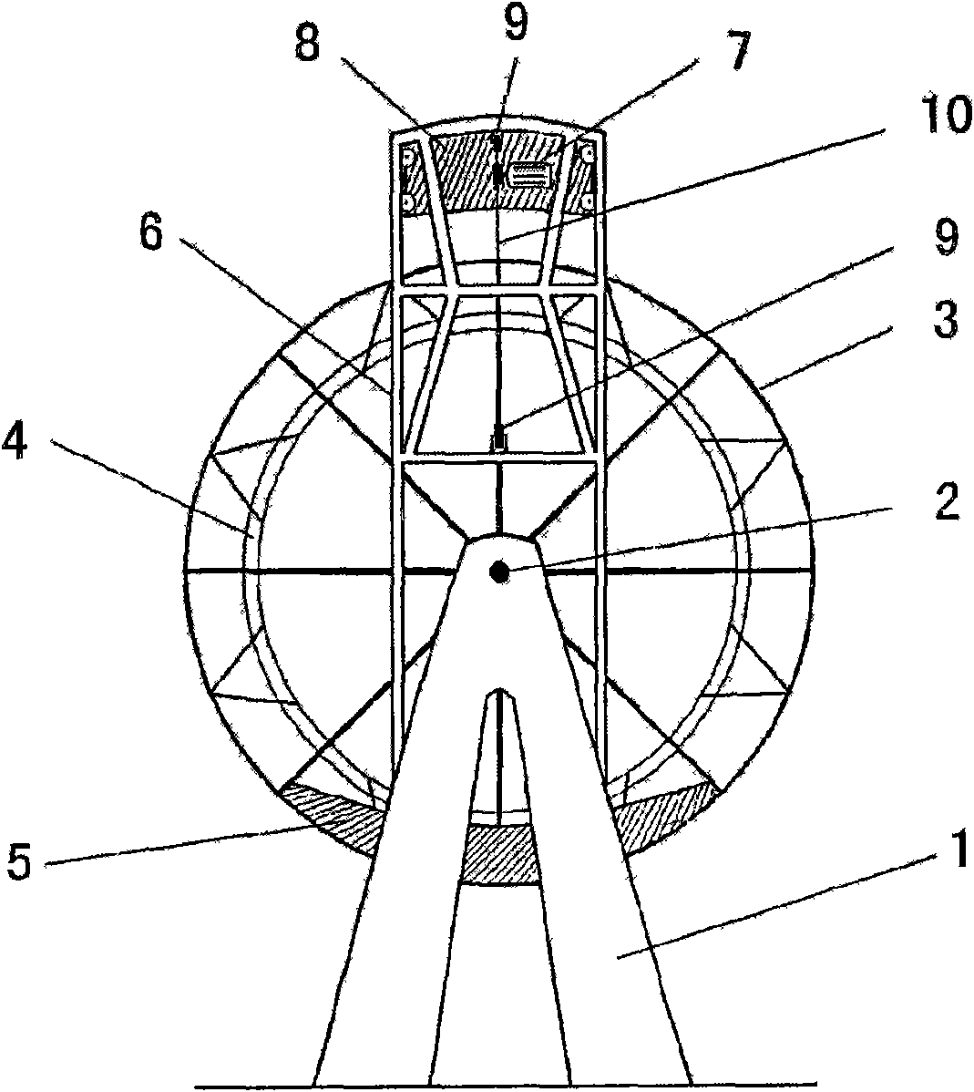
[0023] figure 1 It is a schematic diagram of the mobile wheel device for heavy objects. A main shaft 2 is arranged on the support 1, a runner 3 is arranged on the main shaft 2, and a gear or a belt pulley or a friction wheel 4 with a friction plate is arranged on the runner 3 or on the main shaft 2 on the side of the runner 3 (for connecting power generation Set up the fixed weight 5 on the runner 3, frame 6 is established in the relative direction of the fixed weight 5, and the frame 6 stretches out a distance outside the wheel rim; Track and the chassis with wheels are established in the frame 6, and the motor is established 7 or comprise other objects and constitute movable weight 8 on the chassis. The fixed weight 5 is equivalent to the weight of the movable weight 8 . The motor 7 is connected to an external power supply and a controller controls a switch. Establish pulley 9 and the runner of steel rope 10 and motor 7 in frame 6 to form sling device, when energized, mot...

Embodiment 2

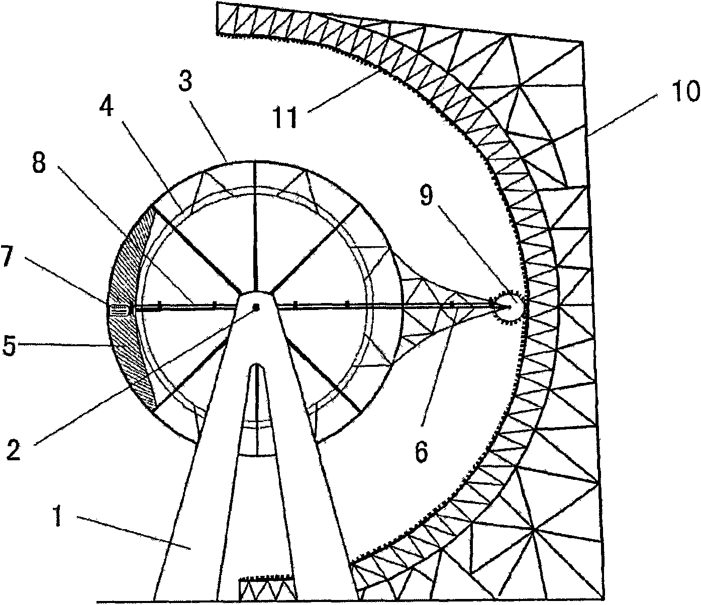
[0030] figure 2 It is a schematic diagram of a gear wheel device. A main shaft 2 is arranged on the support 1, a runner 3 is arranged on the main shaft 2, and a gear or a belt pulley or a friction wheel 4 with a friction plate is arranged on the runner 3 or on the main shaft 2 on the side of the runner 3 (for connecting power generation The relevant device of relevant device); Set up fixed weight 5 on runner 3, motor 7 (external power supply and establish controller control switch) is located on fixed weight 5 and is the component of heavy weight; The relative direction of fixed weight 5 Establish cantilever 6, establish drive shaft 8 beside cantilever 6, gear 9 is established at the end of drive shaft 8, bevel gear conversion rotation direction is all established between drive shaft 8 and motor 6 and gear 9. With the main shaft 2 to the gear 9 as the radius, the inner side of the runner 3 is provided with a semicircular stand 10, and an arc rack 11 is established on the ins...

Embodiment 3

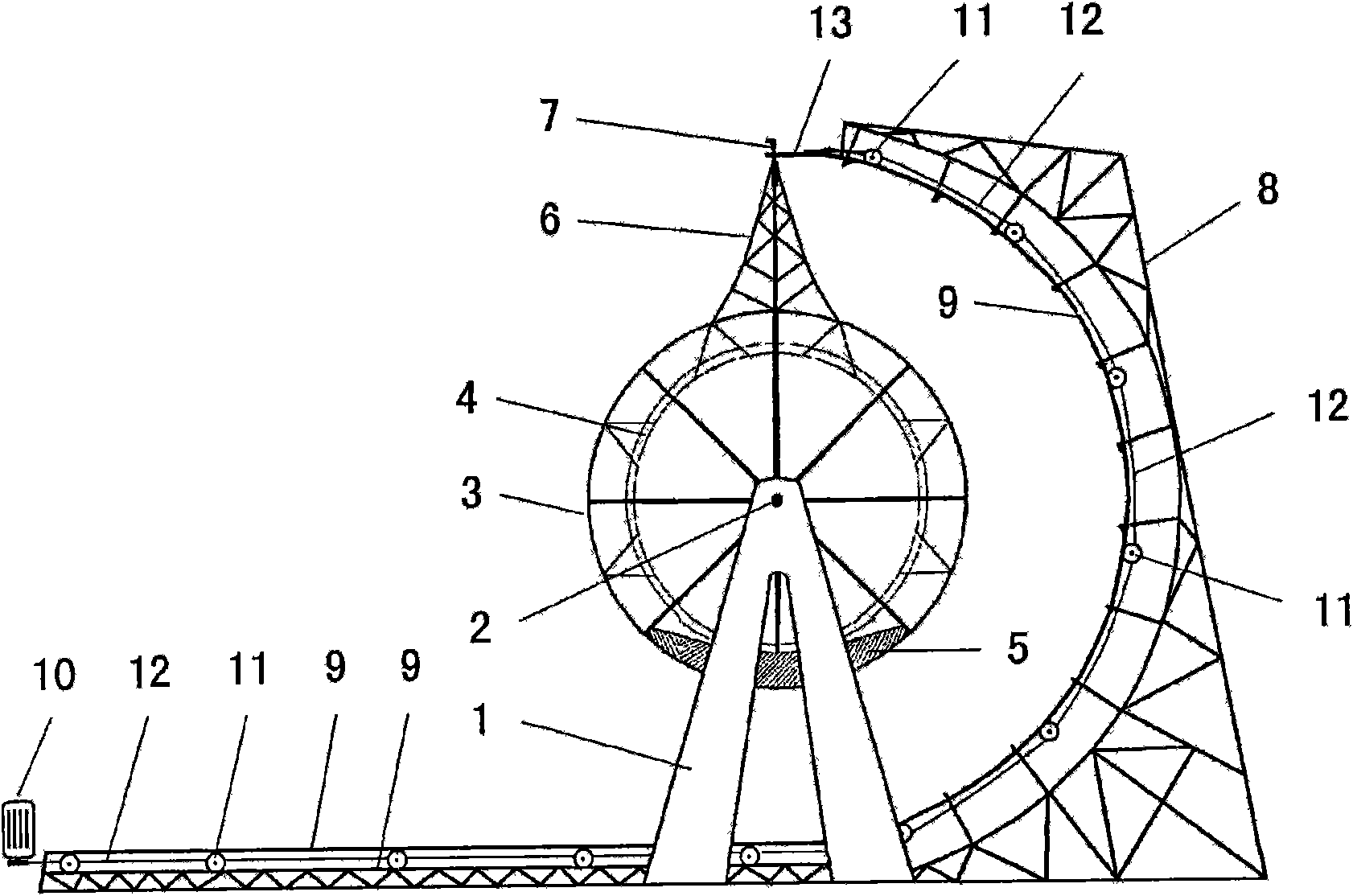
[0036] image 3It is a schematic diagram of the cable-type runner device. A main shaft 2 is arranged on the support 1, a runner 3 is arranged on the main shaft 2, and a gear or a belt pulley or a friction wheel 4 with a friction plate is arranged on the runner 3 or on the main shaft 2 on the side of the runner 3 (for connecting power generation Set up fixed weight 5 on runner 3, establish cantilever 6 in the relative direction of fixed weight 5; Establish automatic telescopic device at the end of cantilever 6, automatic telescopic device establishes two telescopic rods 7; With telescopic rod 7 The length from the main shaft to the end of the cantilever 6 is the radius during the indented state, and a semicircular stand 8 is established on the inside beside the runner 3, and two tracks 9 are established on the inside of the stand 8, and each track 9 has two rails on the left and right. There is an interval between the rails; the two rails 9 extend to the other side of the supp...


PUM


Abstract

The invention relates to a rotating wheel device and power generation equipment. A fixed weight and a movable weight are arranged on a rotating wheel so as to enable the rotating wheel to generate imbalance continuously and rotate by moving the movable weight back and forth, or a weight and at least one cantilever are arranged on the rotating wheel, and an external force is applied to the cantilever so as to enable the rotating wheel to generate imbalance continuously and rotate. The rotating wheel device fully utilizes the lever principle, only needs a small amount of electrical energy to enable the rotating wheel to generate larger mechanical energy, and converted electric energy is more than consumed electric energy. Small parts designed by the rotating wheel device can be used as toysand handicraft articles, and large parts designed by the rotating wheel device can be used as landscape. The power generation equipment formed by combining the rotating device for power generation andan associated device is free from the limitation of natural conditions on installation and the power generation, can carry out the all-weather power generation throughout the year, and has no pollution on environment during the power generation, less investment, short construction periods and low cost of the power generation.

Description

(1) Technical field [0001] The invention relates to the technical field of machinery, in particular to a runner device, and to a power generation device. (2) Background technology [0002] We widely use the wheel device in production and life. Depending on the difference in power, there are many types of runner devices, such as the runner device of the mountain village water mill and the water turbine for hydroelectric power generation, but the existing runner devices must have hydraulic resources; Wheel blades, the existing wind wheel blades are all driven by natural wind resources; while steam turbines consume non-renewable energy such as coal, fuel oil, natural gas, etc., and have relatively large pollution to the environment. The name of the patent application is "gravity generator" (patent application number 200710050192.7). Although its runner device does not require hydraulic resources or wind resources, it does not consume non-renewable energy such as coal, fuel oil...

Claims


Application Information

Patent Timeline
Patent Type & Authority Applications(China)
IPC IPC(8): A63H33/42A63H29/00F03G3/00F03B1/00
Inventor 黄宝文黄郑隽
Owner 黄宝文
Why Eureka
Try Eureka