
Intermediate blank cooling system and cooling control technology

A cooling system and cooling control technology, applied in the field of metallurgy, can solve the problems that the water volume cannot be adjusted automatically according to the needs, the structure and properties of the intermediate billet are unfavorable, and the use effect is not ideal, so as to improve the comprehensive production capacity, facilitate the maintenance of the roller table, reduce the The effect of production organization difficulty

Active Publication Date: 2010-02-10
CISDI ENG CO LTD
View PDF0 Cites 49 Cited by
  • Summary
  • Abstract
  • Description
  • Claims
  • Application Information

AI Technical Summary

Problems solved by technology

The intermediate control cooling system in the form of laminar flow cooling has an adverse effect on the structure and properties of the intermediate billet due to its excessive water volume and high cooling speed.
The intermediate control cooling system in the form of water curtain cannot meet the needs of the production process because the water volume cannot be automatically adjusted according to the needs, and the cooling is uneven, and the temperature difference between the intermediate blanks increases.
[0004] Due to the above-mentioned problems existing in the existing intermediate cooling technology, this controlled cooling technology is the main reason why it has not been widely used at present. Only a few medium and heavy plate production lines such as Baosteel and Jinan Iron and Steel have adopted it in China, and the use effect is not ideal.

Method used


Image

  • Intermediate blank cooling system and cooling control technology
  • Intermediate blank cooling system and cooling control technology
  • Intermediate blank cooling system and cooling control technology

Examples


Embodiment Construction

[0035] The present invention will be further described below in conjunction with specific embodiments, but the present invention is not limited to the following specific methods.

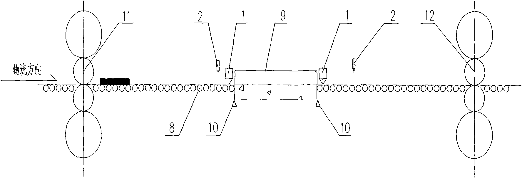
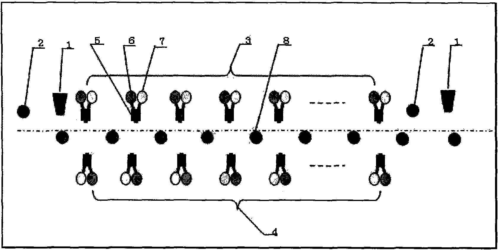
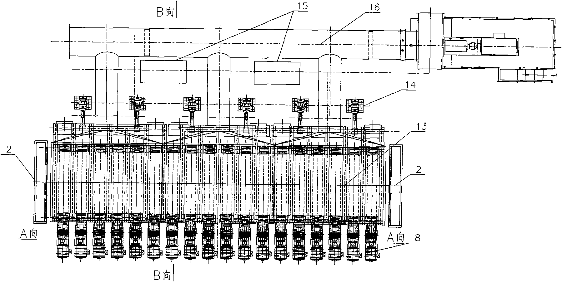
[0036] Such as Figure 1~5 As shown: between the rough rolling mill 11 and the finishing mill 12, a gas mist cooling device body 9 is arranged, and a purging device 1, a pyrometer 2 and a position detector 10 are installed at the entrance and exit thereof. The gas mist cooling device body 9 is composed of an upper cooling header 3 and a lower cooling header 4, the upper cooling header 3 is installed on the upper header frame 17, and the lower cooling header 4 is installed between the conveying rollers 8; An aerosol nozzle 6 and a compressed air pipe 7 are installed on the cooling water pipe 5 of the cooling header 3 and the lower cooling header 4;

[0037] The control valve station 15 makes the upper cooling header 3 and the lower cooling header 4 spray uniform water mist to cool the intermediate b...


PUM


Abstract

The invention belongs to the metallurgy technical field and in particular relates to an intermediate blank cooling system and cooling control technology. The intermediate blank cooling system is characterized in that an aerial fog cooling device body is arranged between a rough mill and a finishing mill. The aerial fog cooling device body is composed of an upper cooling header and a lower coolingheader, and an aerial fog nozzle and a compression air pipe are arranged on the cooling water pipe of the upper cooling header and the lower cooling header; and the on / off control valve and flow control valve of the cooling water pipe and the compression air pipe are connected with a control valve station. The intermediate blank aerial fog cooling technology is controlled by the aerial fog controltechnology sprayed on the cooling header arranged near roller ways at the front and rear of the mills. The invention has fast cooling speed without changing metal performance, water yield regulatingrange is wide and the water yield can be regulated continuously, the cooling speed of the intermediate blank can be precisely controlled, and the invention can be widely applicable to middle and thickplate production line.

Description

technical field [0001] The invention belongs to the technical field of metallurgy, and in particular relates to an intermediate billet cooling system and a cooling control process. Background technique [0002] At present, the domestic and foreign medium and heavy plate production lines have generally adopted the thermomechanical rolling process (TMCP) to produce high-grade medium and heavy plates. The advantage of this process technology is to reduce the cost of high-grade products and obtain products with high strength and high performance. Since the rolling temperature of the intermediate billet needs to be controlled during the rolling process, that is, the intermediate billet must reach a specified temperature before rolling in the second stage or the third stage. The current medium and heavy plate production line basically adopts the method of air cooling on the roller tables before and after the rolling mill, and the cooling time is relatively long. The cooling time d...

Claims


Application Information

Patent Timeline
Patent Type & Authority Applications(China)
IPC IPC(8): B21B45/02B21B37/74B21B37/76
Inventor 李宏图胡元祥刘歌冉瑞生李剑王强
Owner CISDI ENG CO LTD
Learn More