Self-ventilation cooling device of external rotor permanent magnet synchronous machine

A permanent magnet synchronous motor, outer rotor technology, applied in cooling/ventilation devices, electromechanical devices, electric components, etc., can solve the problems of inability to install fans, high overall heat dissipation requirements, and difficulty in stator heat dissipation, to maintain smooth flow, ensure Continuous working reliability, good air cooling effect

Inactive Publication Date: 2010-02-10
HUAZHONG UNIV OF SCI & TECH
View PDF1 Cites 23 Cited by
  • Summary
  • Abstract
  • Description
  • Claims
  • Application Information

AI Technical Summary

Problems solved by technology

However, this structure is not suitable for external rotor permanent magnet motors, which is determined by the particularity of the structure: on the one hand, the rotor is external, and the motor shaft is fixed, so it is impossible to install a fan on the shaft; Difficult heat dissipation, higher requirements for overall heat dissipation
It can be seen that the design based on the traditional ventilation cooling structure cannot meet the heat dissipation requirements of the outer rotor permanent magnet synchronous motor

Method used


Image

  • Self-ventilation cooling device of external rotor permanent magnet synchronous machine
  • Self-ventilation cooling device of external rotor permanent magnet synchronous machine
  • Self-ventilation cooling device of external rotor permanent magnet synchronous machine

Examples


Embodiment Construction

[0017] The embodiments will be described in detail below in conjunction with the accompanying drawings.

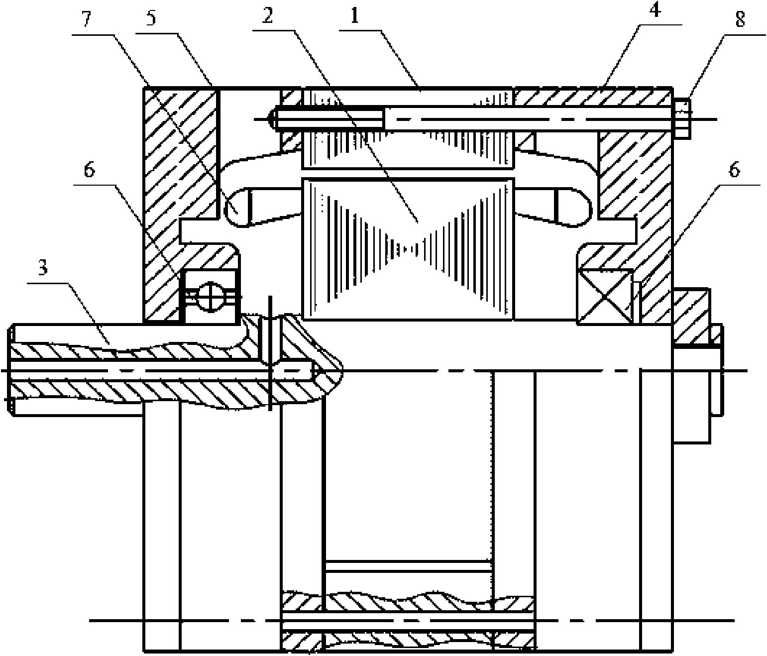
[0018] figure 1 It is a schematic diagram of the overall structure of the cooling air passage shown in the longitudinal section of the motor. The cooling air passage includes: the front cover 4, the axial straight air passage of the stator core 2, the inner air passage of the rotor core 3 and the rear end cover 5.

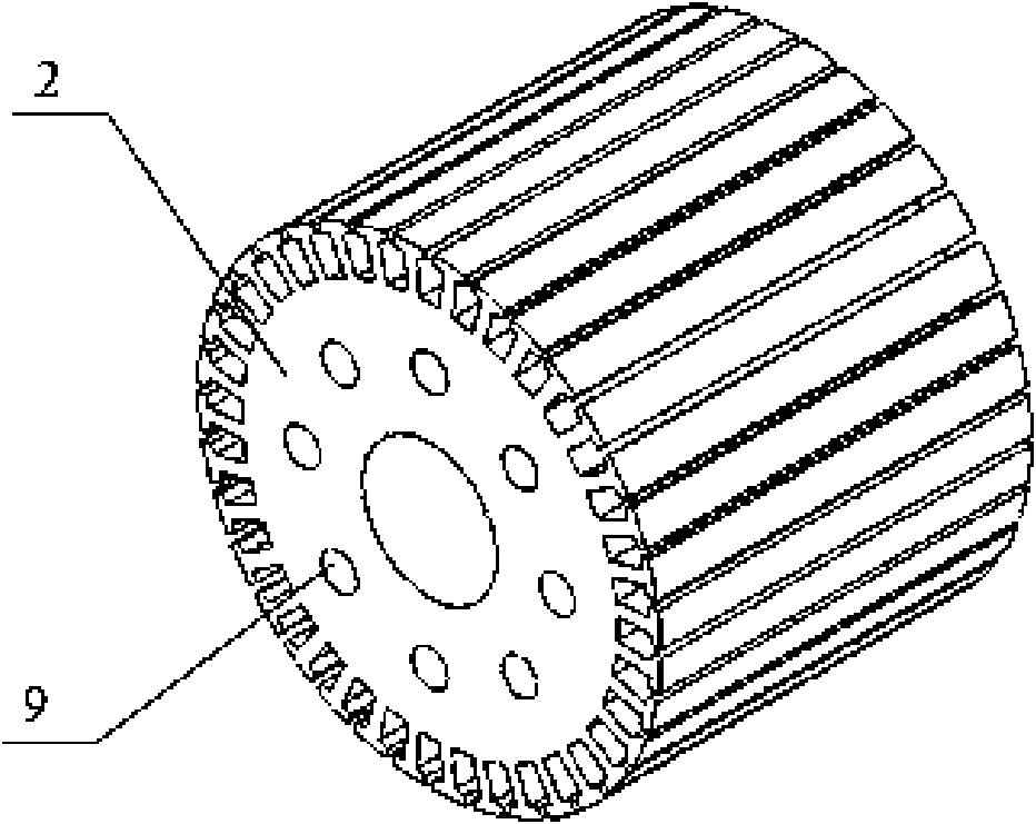
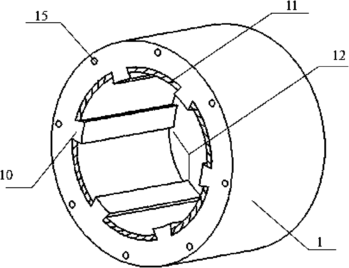
[0019] The front and rear end covers 4 and 5 are installed at both ends of the outer rotor core 1 of the motor, are fixedly connected with the rotor core 1 by screws 8, and are set on the motor shaft 3 through the bearing 6, and the end covers are of a centrifugal fan structure. The stator core 2 is perforated to form an axial ventilation channel. The inner side of the rotor 1 relies on protruding rotor teeth to form a plurality of air passages, which can be designed as axial straight air passages or spiral air passages according to different examples.

[002...


PUM


Abstract

The invention provides a self-ventilation cooling device of external rotor permanent magnet synchronous machine. A front end cover and a back end cover, both of which are provided with fan wheels therein, are respectively mounted at the two ends of an outer rotor iron core of a motor. The fan wheel is provided with a wheel hub and a plurality of vanes; and the wheel hub is sleeved on a motor shaft. Gaps are among the circumference of the front end cover and the vanes. The end surface of the front end cover is provided with an annular air inlet. The circumference of the back end cover is connected with the vanes; and air outlet is formed between the adjacent vanes on the circumference of the back end cover. The stator iron core is provided with a plurality of stator iron core vent holes therein. The rotor gears at the inner sidewall of the outer rotor iron core are projected out of the permanent magnet; and outer rotor vent channels are formed between the adjacent rotor gears. The invention sucks in the cool air from the centrifugal fan on the front end cover to direct air-cool the motor and finally exhausts the air with the motor inner heat energy out of the motor body by the centrifugal fan on the back end cover. The invention can keep the smooth flow of the cooling air in the inner part of the motor, thereby having good air-cooling effect and ensuring continuous work reliability of the permanent magnet motor.

Description

technical field [0001] The invention relates to the technical field of motor cooling, in particular to a self-ventilating cooling device for an outer rotor permanent magnet motor. Background technique [0002] Permanent magnet synchronous motor is a new type of direct drive torque servo motor. Because of its advantages of large output torque, low speed, compact structure, high efficiency and energy saving, it is especially suitable for low-speed driving occasions. It is used in metallurgical machinery, electric vehicles, and CNC machine tools. Equipment and many other fields have been widely used. For permanent magnet motors, the overall performance of the motor depends largely on the permanent magnets, and the heating of the motor will inevitably have an adverse effect on the stability of the permanent magnet performance. Therefore, it is necessary to use a reasonable cooling method to control the temperature rise of the motor. [0003] Permanent magnet motors have high to...

Claims


Application Information

Patent Timeline
Patent Type & Authority Applications(China)
IPC IPC(8): H02K9/04H02K1/20H02K5/20H02K1/32
Inventor 杨凯冯垚径
Owner HUAZHONG UNIV OF SCI & TECH
Why Eureka
Try Eureka