66kv optically-controlled water-cooling thyristor valve box

A thyristor valve, thyristor technology, applied in the direction of electrical components, electric solid devices, circuits, etc., can solve problems such as unfavorable repair and maintenance, circuit influence, etc., to achieve compact structure, reduce interference, and reduce the effect of parts types

Active Publication Date: 2010-02-17
辽宁荣信兴业智能电气有限公司
View PDF6 Cites 7 Cited by
  • Summary
  • Abstract
  • Description
  • Claims
  • Application Information

AI Technical Summary

Problems solved by technology

However, at present, the waterway and circuit of the valve group are arranged alternately, which is not conducive to inspection and maintenance, and once the water leaks, it will affect the circuit

Method used


Image

  • 66kv optically-controlled water-cooling thyristor valve box
  • 66kv optically-controlled water-cooling thyristor valve box
  • 66kv optically-controlled water-cooling thyristor valve box

Examples


Embodiment 1

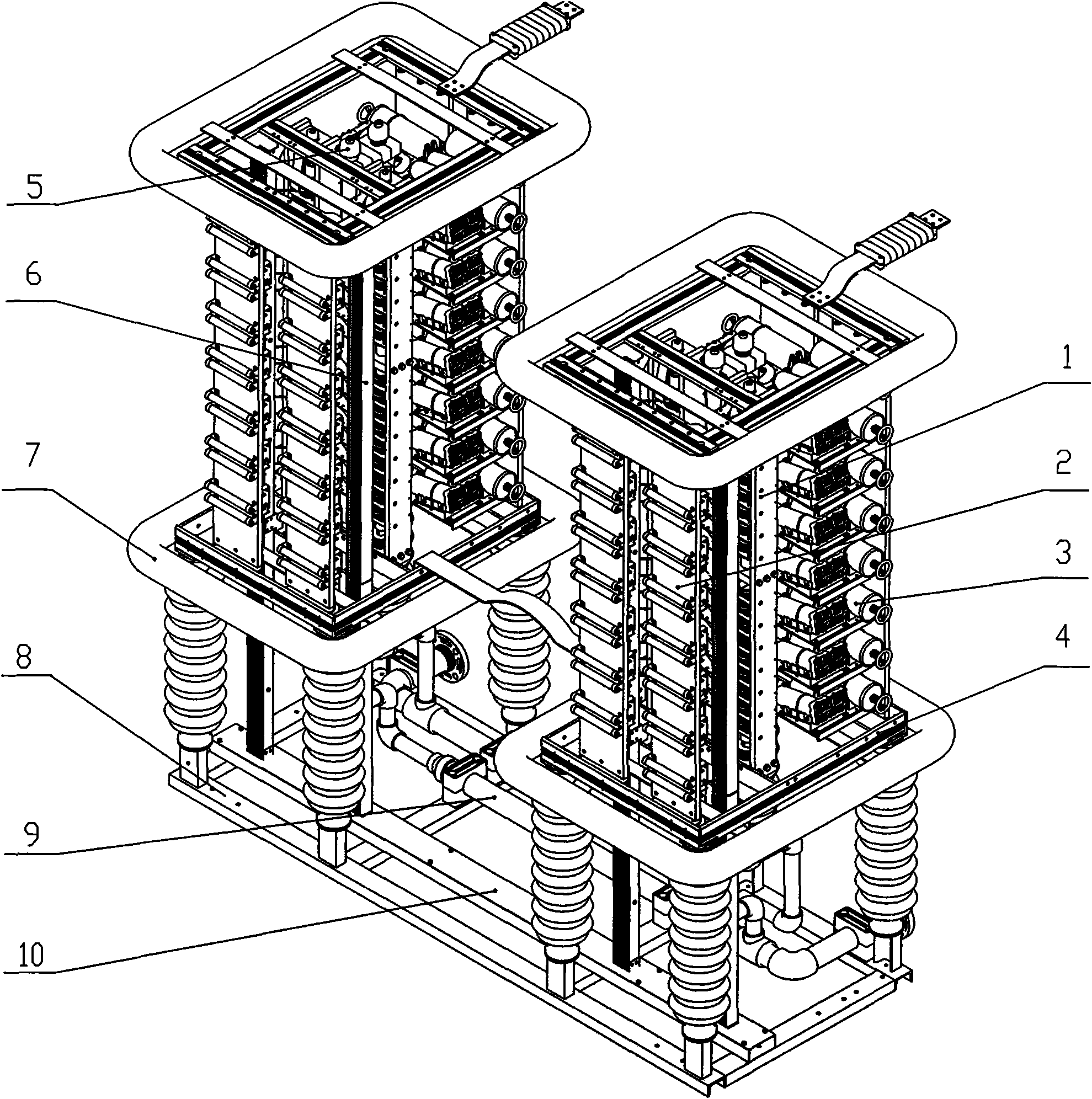
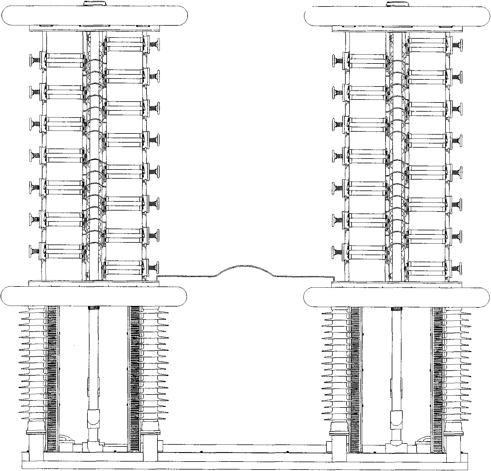
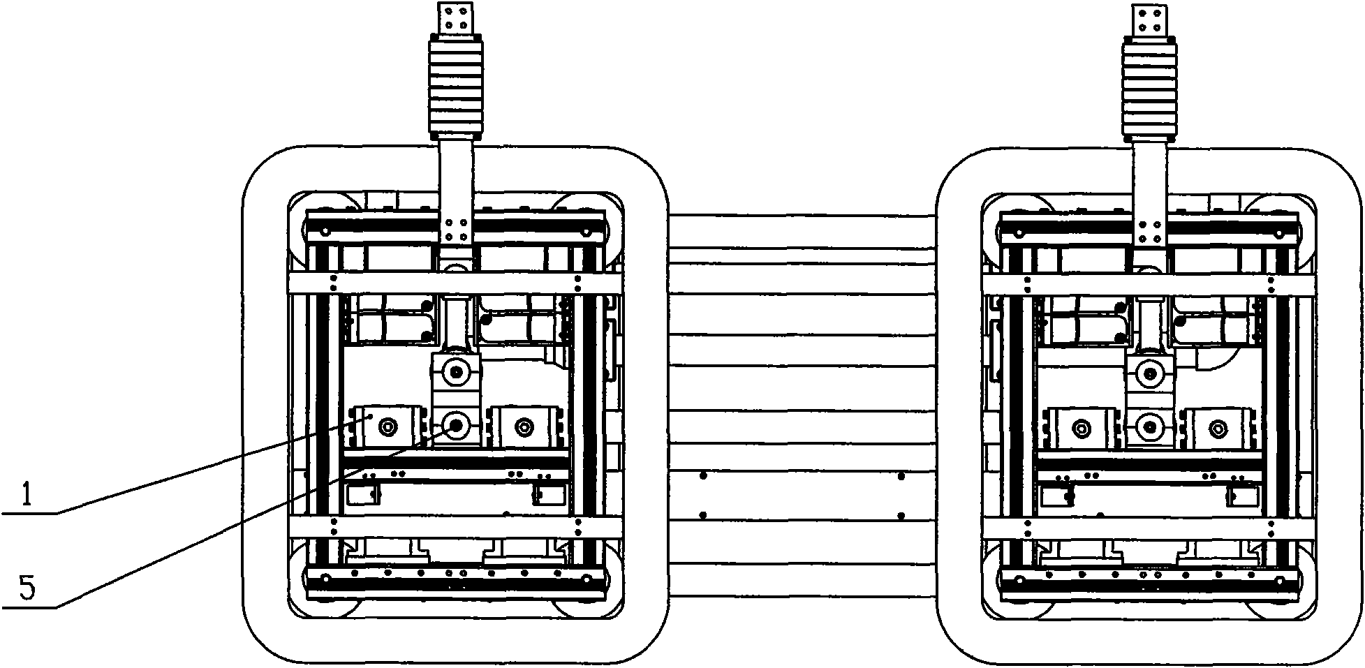
[0027] See Figure 1-Figure 5 , 66kV light-controlled water-cooled thyristor valve group, the valve group adopts a two-body vertical structure, consisting of two left and right valve units to form a single-phase valve group, and the left and right valve units are connected by copper foil soft row. Each valve unit is composed of a thyristor unit 1 , a return board unit 2 , a RC protection unit 3 , a frame unit 4 , an internal water pipe unit 5 , a wiring trough unit 6 , and a pressure equalizing ring unit 7 . The thyristor unit 1 that needs water cooling and the water-cooled resistors in the RC protection unit 3 are arranged on both sides of the internal water pipe unit 5, and are located in the middle of the valve unit; other components of the RC protection unit 3 that do not need water cooling except the water-cooled resistor , the return board unit 2, the wiring trough unit 6, and the pressure equalizing ring unit 7 are all located around the valve unit. Each unit is connec...

Embodiment 2

[0030] refer to figure 1 , 35kV light-controlled water-cooled thyristor valve group, the valve group adopts a single vertical structure, consisting of a thyristor unit 1, a return board unit 2, a resistance-capacitance protection unit 3, a frame unit 4, an internal water pipe unit 5, and a wiring trough unit 6 , The pressure equalizing ring unit 7 is composed. The thyristor unit 1 that needs water cooling and the water-cooling resistance in the resistance-capacity protection unit 3 are arranged on both sides of the internal water pipe unit 5, and are located in the middle of the valve unit; other components of the resistance-capacity protection unit 3 that do not need water cooling except for the water-cooled resistance, , the return plate unit 2, the wiring trough unit 6, and the pressure equalizing ring unit 7 are all located around the valve group. Each unit is connected with the frame unit 4 through the epoxy glass cloth board. The valve body is connected to the base 8 t...


PUM


Abstract

The invention relates to an optically-controlled water-cooling radiating thyristor valve box which is characterized in that the valve box is in a dual body vertical structure; a left valve unit and aright valve unit are connected in series to form a uniphase valve box; the left valve unit and the right valve unit are connected by a copper foil soft contactor; a water pipe unit of each valve unitis mounted in the middle of the valve unit, and a thyristors unit needing water cooling and a water-cooling resistance of a resistive-capacitive protective unit are mounted at two sides of the water pipe unit; other elements of the resistive-capacitive protective unit without needing of water cooling except the water-cooling resistance, a cabling channel unit, an equalizing ring unit are mounted at the periphery of the valve box. The water-cooling resistance and a damping capacitance are mounted on a resistive-capacitive bracket side by side in a concentrated layout manner. The resistive-capacitive protective unit uses modular design, and can assemble two eudipleural resistive-capacitive protective units by arranging the same water-cooling resistance and the damping capacitance on the resistive-capacitive bracket. The invention has the advantages of high reliability, small occupied area, separately arrangement of circuit and waterway and pure water cooling.

Description

technical field [0001] The invention relates to a water-cooled and heat-dissipating light-controlled thyristor valve group. The valve group is used in electric power, metallurgy and all other fields using light-controlled thyristors as core devices, and can be used for light-controlled thyristor valve groups with voltage levels of 66kV and above. Background technique [0002] Thyristors are currently the most widely used valve components. By controlling the firing angle of thyristors, the impedance can be continuously adjusted, which can enhance the power transmission capacity of the system, improve system stability, damp power oscillations, and suppress subsynchronous oscillations. The thyristor valve body usually has to withstand high voltage and high current, which needs to be realized by series and parallel connection of multiple thyristors. The thyristor valve group is the core component of the dynamic reactive power compensation device in the power system. [0003] Th...

Claims


Application Information

Patent Timeline
Patent Type & Authority Applications(China)
IPC IPC(8): H01L25/07H01L23/473H01L23/367
CPCH01L2924/0002
Inventor 司明起薛轶宁刘国恩龙浩丁雅丽杜纯钢杨旭
Owner 辽宁荣信兴业智能电气有限公司
Why Eureka
Try Eureka