
Filtering module inhibiting common mode noise and differential mode noise

A filtering module and common-mode suppression technology, which is applied in the field of filter modules and filter circuit modules for suppressing common-mode noise and differential-mode noise, can solve problems such as poor filtering effect, narrow effective frequency band, and large volume, and achieve filtering effect Good, uniform waveform, small size effect

Inactive Publication Date: 2010-02-17
上海爱瑞科技发展有限公司
View PDF0 Cites 17 Cited by
  • Summary
  • Abstract
  • Description
  • Claims
  • Application Information

AI Technical Summary

Problems solved by technology

[0005] The disadvantages of the above-mentioned existing filter modules are summarized as follows: large size; narrow effective frequency band, poor filtering effect; high price; one-way filtering function

Method used


Image

  • Filtering module inhibiting common mode noise and differential mode noise

Examples


Embodiment Construction

[0014] The present invention is specifically described below in conjunction with the circuit diagram: the filter module is used for filtering noise of the power supply on a DC 110V power supply.

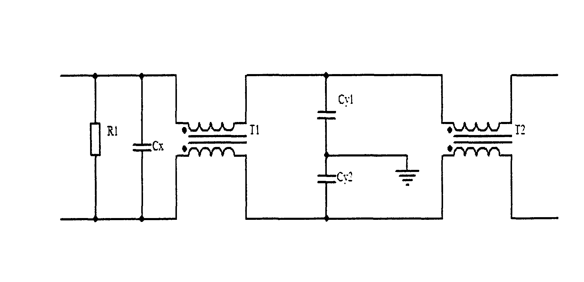
[0015] Such as figure 1 , the connection structure of the circuit is to connect a parallel branch composed of a discharge resistor (R1) and a differential mode capacitor (Cx) between the positive and negative poles of the common mode inductor (T1) close to the DC power input terminal, and the other end flows through The Y capacitors (Cy1) and (Cy2) are grounded; one end of the differential mode inductor (T2) is connected to the output terminal of the DC power supply, and the other end is connected to the positive and negative lines flowing through the common mode capacitors (Cy1) and (Cy2). The above connection can It can be seen that through the two different inductances connected in series T1 and T2, the differential mode noise in the high frequency band and the low frequency band ...


PUM

PropertyMeasurementUnit
Resistanceaaaaaaaaaa
Capacitanceaaaaaaaaaa

Abstract

The invention discloses a filtering module inhibiting common mode noise and differential mode noise, comprising a first-level filtering module and a second-level filtering module. On the input end ofa common mode inductance (T1), which is near the power supply, a parallel branch composed of a disparaging resistance (R1) and a differential mode inductance (Cx) is connected between an anode and a cathode, and the other end is grounded by Y capacitance (Cy1) and capacitance (Cy2); and one end of a filtering inductance (T2) is connected with the output end of a direct-current power supply, and the other end is connected with a positive wire and a negative wire of the first-level filtering module. The above filtering module adopts the form of two-pole filtering circuit to increase the width ofthe effective filtering frequency band, lower volume and lower cost, filtering effect is favourable and the invention has the function of bidirectional filtering.

Description

technical field [0001] The invention relates to the technical field of a filter circuit module for filtering power supply noise, in particular to the technical field of a filter module for suppressing common-mode noise and differential-mode noise. Background technique [0002] Electromagnetic Compatibility (Electromagnetic Compatibility, EMC) refers to the ability of a device or system to operate in compliance with the requirements in its electromagnetic environment without causing unbearable electromagnetic interference to any equipment in its environment. Various operating electrical equipment are related to each other and affect each other in three ways: electromagnetic conduction, electromagnetic induction and electromagnetic radiation. Under certain conditions, they will cause interference, influence and harm to the operating equipment and personnel. [0003] The filter technology adopted by the power supply filter circuit in the prior art has the following scheme, a fi...

Claims


Application Information

Patent Timeline
IPC IPC(8): H02M1/14
Inventor 胡夕祝丁晨谭平
Owner 上海爱瑞科技发展有限公司
Learn More