
Communication terminal device, communication control device, radio communication system, and resource allocation request method

A technology for a wireless communication system and a communication terminal, which is applied in the field of communication terminal devices, can solve the problems of requiring time, unable to effectively utilize UL resources, and effectively utilizing resources with low utilization frequency, and achieves the effect of effectively utilizing resources.

Inactive Publication Date: 2010-02-17
SHARP KK
View PDF0 Cites 2 Cited by
  • Summary
  • Abstract
  • Description
  • Claims
  • Application Information

AI Technical Summary

Problems solved by technology

[0034] However, in the first method, it is necessary to secure a special random access channel area for the synchronized mobile station, and it cannot be said that resources are effectively used when the frequency of use of the random access channel is low.
In addition, there is a problem that the procedure for requesting new resources takes time because random access that may collide with other mobile stations is used.
Furthermore, in the second method, it is necessary to always secure a resource for transmitting a control signal for each mobile station, and there is a problem that resources cannot be effectively used when the frequency of use of the control signal is low.
In this way, no matter which method is used, there is a problem that UL resources cannot be effectively utilized

Method used


Image

  • Communication terminal device, communication control device, radio communication system, and resource allocation request method
  • Communication terminal device, communication control device, radio communication system, and resource allocation request method
  • Communication terminal device, communication control device, radio communication system, and resource allocation request method

Examples


no. 1 Embodiment approach

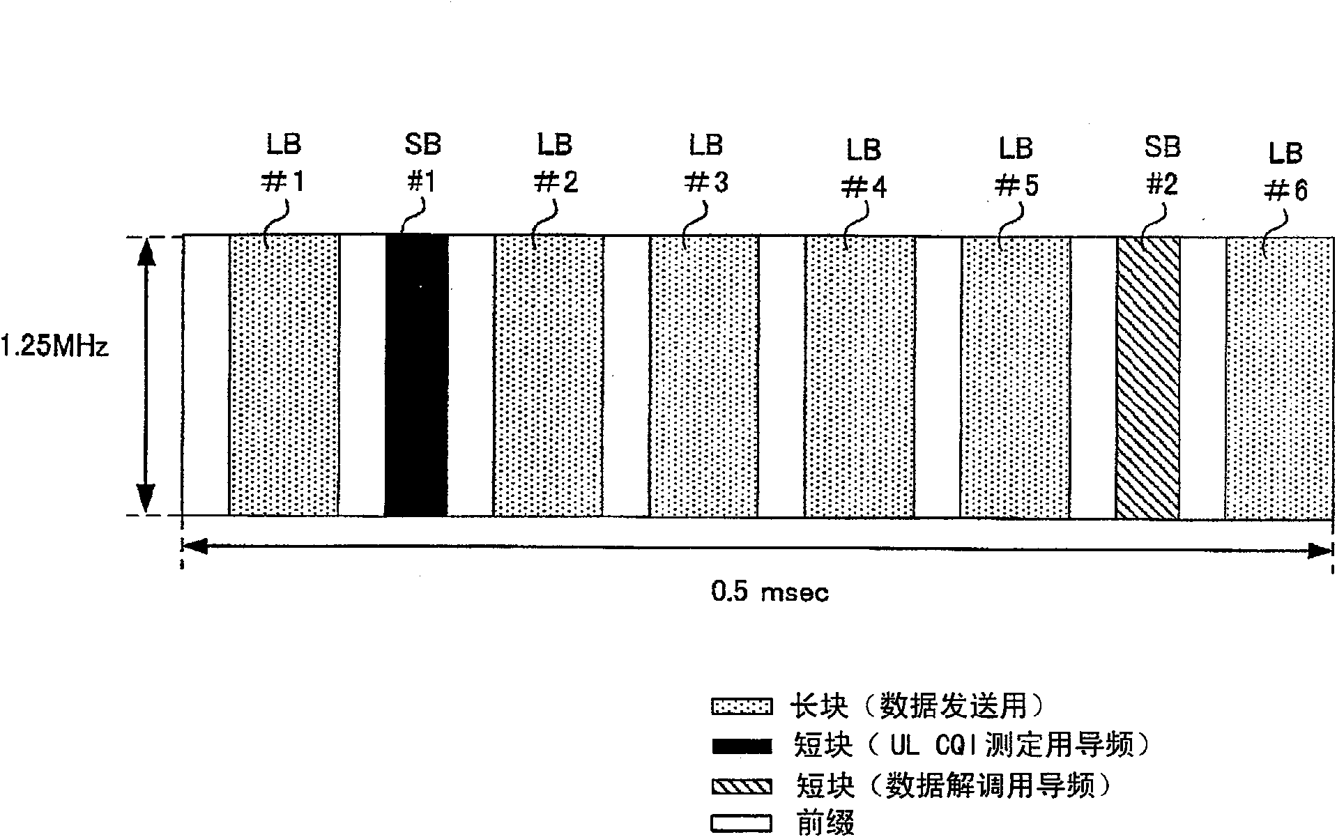
[0117] In the first embodiment, taking a mobile station in DTX / DRX mode as an example, using Figure 7 Describe in detail. In this embodiment, a mode in which transmission of a pilot signal is stopped and a resource request (UL RR) is performed will be described. Figure 7 It is a sequence diagram showing an example of a pilot signal variation accompanying a UL resource request in the first embodiment. Figure 7 A sequence diagram of a mobile station (UE) is shown on the left side of , and a sequence diagram of a base station (NB) is shown on the right side. exist Figure 7 In , long blocks for data transmission are indicated by dots, short blocks of pilots for UL CQI measurement are indicated by blacked-out areas, and short blocks of pilots for data demodulation are indicated by oblique lines, which are used in the following embodiments. The same is true for the same figure. Below, use Figure 6 , Figure 7 The operation of the UL RR will be described.

[0118] Such as...

no. 2 Embodiment approach

[0134] Next, as a second embodiment, taking a mobile station in DTX / DRX mode as an example, using Figure 9 Describe in detail. In this embodiment, a mode in which a resource request (UL RR) is performed by stopping transmission of a pilot signal and restarting it within a predetermined period will be described. Figure 9 It is a sequence diagram showing an example of a pilot signal variation accompanying a UL resource request in the second embodiment. Figure 9 A sequence diagram of a mobile station (UE) is shown on the left side of , and a sequence diagram of a base station (NB) is shown on the right side. Below, use Figure 6 , Figure 9 The operation of the UL RR will be described.

[0135] Such as Figure 9 As shown, assume the following situation ( Figure 9 pilot signal transmission): the mobile station 200 in the DTX / DRX mode does not always communicate, but in order to maintain synchronization, at a certain time frequency position, within the period during which...

no. 3 Embodiment approach

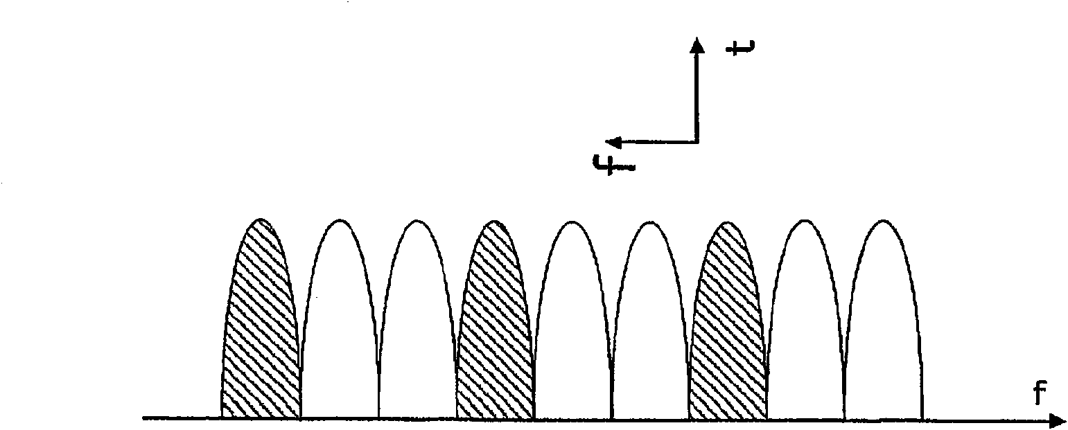
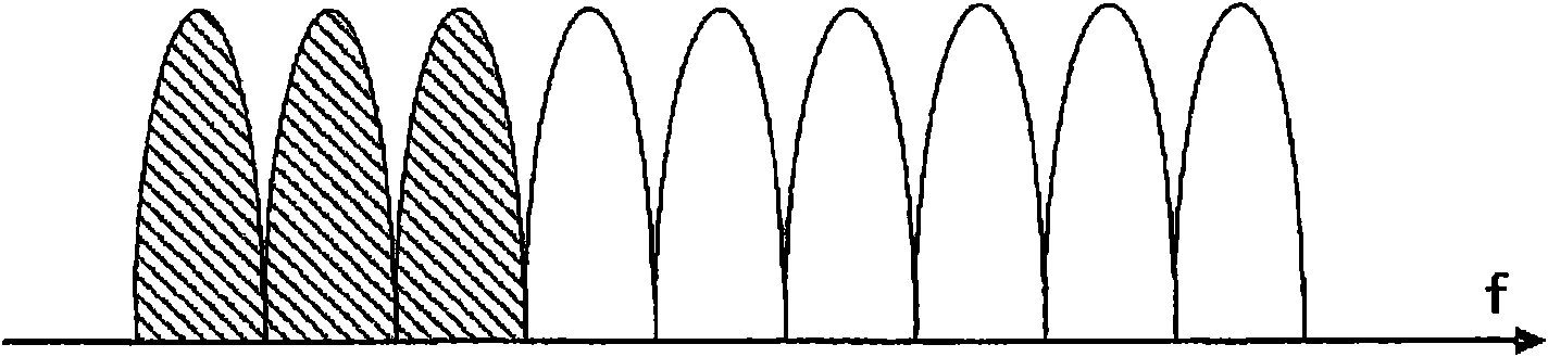
[0152] Next, as a third embodiment, taking a mobile station in DTX / DRX mode as an example, using Figure 11 Describe in detail. In this embodiment, a mode in which transmission of a pilot signal is stopped and a resource request (ULRR) is performed when the transmission frequency band of the pilot signal is changed with time will be described. Figure 11 This is a sequence diagram showing an example of a pilot signal variation accompanying a UL resource request in the third embodiment. Figure 11 A sequence diagram of a mobile station (UE) is shown on the left side of , and a sequence diagram of a base station (NB) is shown on the right side. Below, use Figure 6 , Figure 11 The operation of the ULRR will be described.

[0153] Such as Figure 11 As shown, assume the following situation ( Figure 11 Pilot signal transmission): The mobile station 200 in the DTX / DRX mode does not always communicate, but in order to at least maintain synchronization, the time frequency pos...


PUM


Abstract

A communication terminal device can send a resource allocation request to a communication control device without allocating any dedicated resource allocation for the resource request. The communication terminal device is applied to a radio communication system in which the communication control device allocates resource used when performing radio transmission from the communication terminal device(200) to the communication control device (100). The communication terminal device includes: a judging unit (210) which judges whether to send a resource request to the communication control device (100); and a signal control unit (211) which transmits a signal used for maintaining time / frequency synchronization with the communication control device (100) to the communication control device (100)by a first transmission procedure for maintaining the synchronization. If the judging unit (210) has judged to make a resource request, the signal control unit (211) transmits the signal to the communication control device (100) by a second transmission procedure indicating the resource request.

Description

technical field [0001] The present invention relates to a communication terminal device, a communication control device, a wireless communication system, and a resource allocation request method applied to a wireless communication system. The communication control device in the wireless communication system allocates resources from the communication terminal device to the Resources used when the communication control device performs wireless transmission. Background technique [0002] In 3GPP (3rd Generation Partnership Project, 3rd Generation Partnership Project), RAT (Radio Access Technology, Wireless Access Technology), W-CDMA (Wideband-Code Division Multiple Access, Broadband Code Division Multiple Access) was standardized, and services were started sequentially (Non-Patent Document 1). Furthermore, the evolution of the third generation RAT (Evolved Universal Terrestrial Radio Access, hereinafter referred to as "EUTRA") and the evolution of the third generation RAT acce...

Claims


Application Information

Patent Timeline
IPC IPC(8): H04W72/12H04W76/02H04B1/707H04J11/00H04J13/00
CPCH04L5/0007H04L5/0091H04W56/0005H04W72/0413H04W72/1284H04L12/40013H04J13/0059H04L5/0048H04L1/0026H04L27/2613H04W72/21
Inventor 菅原靖夫山田升平中岛大一郎加藤恭之上村克成王和丰今村公彦
Owner SHARP KK
Features
  • Generate Ideas
  • Intellectual Property
  • Life Sciences
  • Materials
  • Tech Scout
  • Unparalleled Data Quality
  • Higher Quality Content
  • 60% Fewer Hallucinations
Learn More