Seal structure between wind chamber and the lower part of sintering ring cold machine trolley of steel and iron plant

A technology of sintering annular cooler and sealing structure, which is applied in the treatment of discharged materials, furnace types, furnaces, etc., can solve the problems of not realizing the full recycling of flue gas, affecting the utilization temperature of waste heat flue gas, and reducing the quality of circulating flue gas. , to achieve the effect of reducing the power consumption rate of the plant, reducing the strength and prolonging the life.

Active Publication Date: 2010-02-24
ZHEJIANG XIZI UNITED ENG
View PDF3 Cites 9 Cited by
  • Summary
  • Abstract
  • Description
  • Claims
  • Application Information

AI Technical Summary

Problems solved by technology

However, the annular cooler is not a finished part. During the operation of the annular cooler, there is a situation of moving to each different part, so that the sealing becomes a bottleneck. The crux of the problem: there is a large air leakage between the lower part of the trolley and the air chamber. 30-50% of the wind is exposed from the lower part, and a large amount of hot air leaks out so that the full recycling of flue gas in the true sense cannot be realized. In order to supplement the leaked air volume, a large amount of cold air must be supplemented, and at the same time, the selection of the flue gas recirculation fan must be enlarged , which reduces the quality of the circulating flue gas, consumes the electric energy of the motor in vain, and affects the utilization temperature of the waste heat flue gas, thereby reducing the quality of the steam generated by the boiler and affecting the entire power generation system

Method used


Image

  • Seal structure between wind chamber and the lower part of sintering ring cold machine trolley of steel and iron plant
  • Seal structure between wind chamber and the lower part of sintering ring cold machine trolley of steel and iron plant

Examples


Embodiment

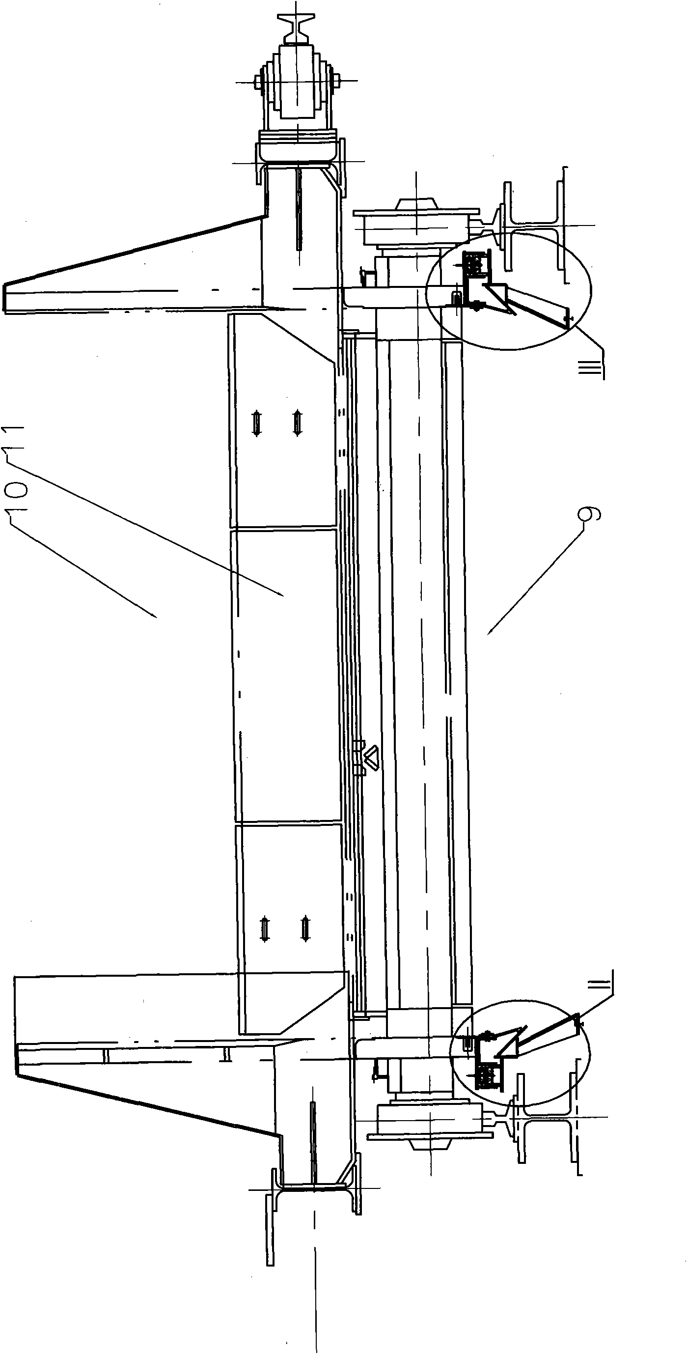
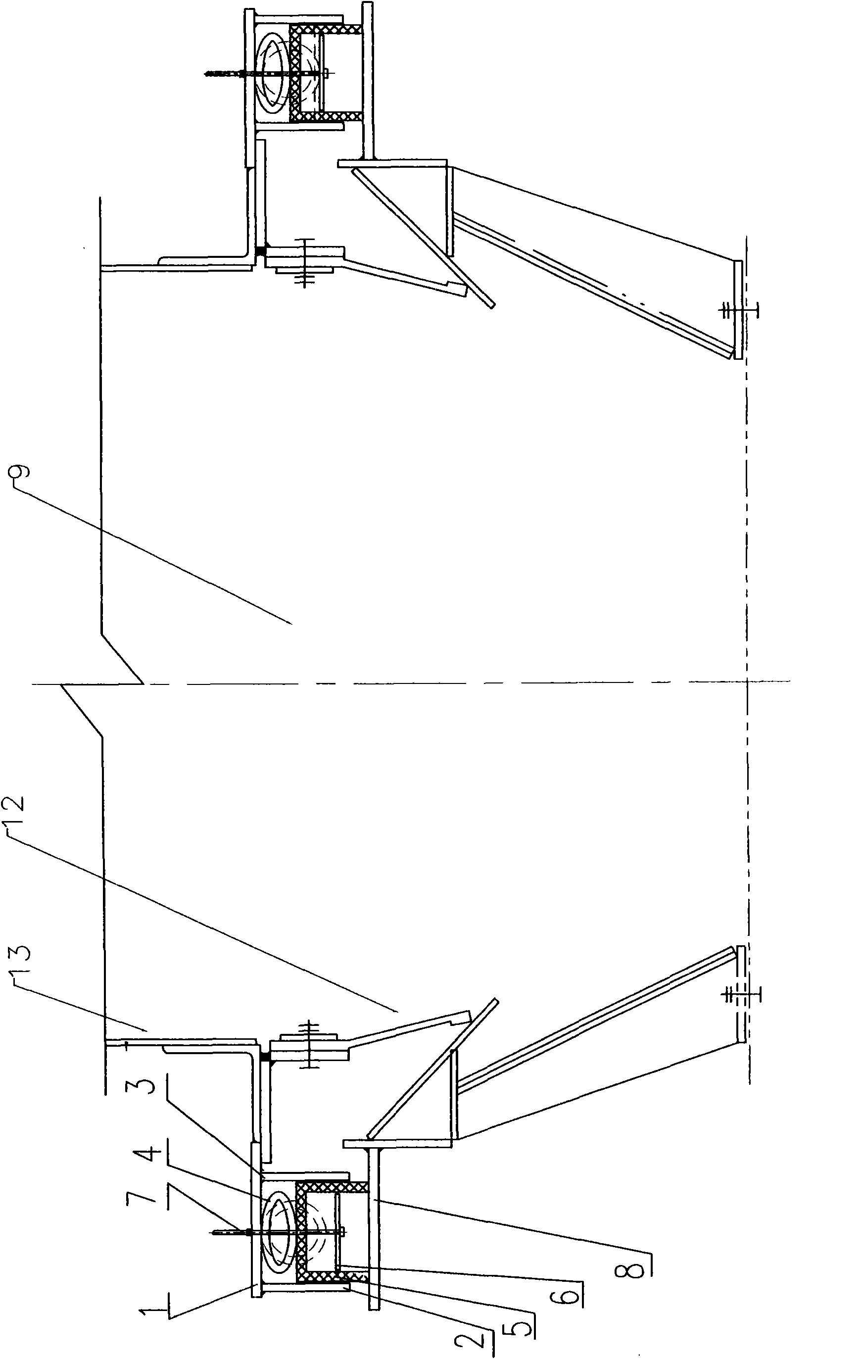
[0022] Such as figure 1 , figure 2 As shown, this embodiment provides a sealing structure between the lower part of the sintering ring cooler trolley and the bellows designed in the present invention, mainly including the outer seal, the seal contact plate 8 and the inner seal rubber 12, which are characterized in that The outer seal is composed of a seal support 1, an outer limit plate 2, an inner limit plate 3, an elastic rubber cylinder 4, a sealing groove rubber 5, a supporting plate 6, and an adjustable connecting screw 7. The supporting plate 6 is set on the sealing Groove rubber 5, and through the adjustable connecting screw 7 and seal support 1 adjustable connection, between the seal groove rubber 5 and seal support 1, there is an elastic rubber cylinder 4, the inner limit plate 3 and The outer limit plate 2 is respectively set on the inner and outer sides of the sealing groove rubber 5, and the outer sealing member and the inner sealing rubber 12 are fixed on the lo...


PUM


Abstract

The invention discloses a seal structure between a wind chamber and the lower part of a sintering ring cold machine trolley of a steel and iron plant, which mainly comprises an outer seal piece, a seal contact plate and inner-side seal rubber, wherein the outer seal piece consists of a seal piece strut member, an outer limit plate, an inner limit plate, an elastic rubber cylinder, rubber in the shape of a seal groove, a support plate and an adjustable connection screw rod, the support plate is arranged in the rubber in the shape of a seal groove and is connected with the seal piece strut member through the adjustable connection screw rod in an adjustable way, outer seal is realized through the rubber in the shape of a seal groove and the seal contact plate, and inner seal is realized through the inner-side seal rubber. The invention improves the efficiency of smoke recycle and the quality of smoke utilization, fully recycles smoke, effeciently uses cold residual heat of sintering rings, decreases maintenance cost of the seal piece and shortens service life.

Description

technical field [0001] The invention relates to a sintering ring cooler equipment technology used in a steel plant, in particular to a sealing structure between the lower part of a sintering ring cooler trolley and an air box in a steel plant. Background technique [0002] In the process of iron and steel production, the energy consumption of the sintering process accounts for about 10% of the total energy consumption, ranking second only to the iron-making process. In the total energy consumption of the sintering process, nearly 50% of the heat energy is discharged into the atmosphere in the form of sensible heat of the sintering machine flue gas and cooler exhaust gas. Because the temperature of the exhaust gas of the sintering ring cooler is not high, only 150 ~ 450 ℃, plus the limitations of the previous waste heat recovery technology, it has been ignored for a long time. [0003] The sealing technology of the sintered ring cooler is one of the key technologies for the ...

Claims


Application Information

Patent Timeline
Patent Type & Authority Applications(China)
IPC IPC(8): F27B21/08F27D15/02
Inventor 周勇平周海平金雷何世民
Owner ZHEJIANG XIZI UNITED ENG
Why Eureka
Try Eureka