
Stray energy power supplying method of electrical equipment status monitoring wireless sensing system and device thereof

A technology of electrical equipment and wireless sensing, applied in battery circuit devices, electromechanical devices, circuit devices, etc., can solve the adverse effects of long-term safe operation of electrical equipment, unused vibration energy, thermal energy and magnetic leakage energy, unstable bus current, etc. problems, to achieve significant economic value and social value, heat dissipation and cooling stray losses, and reduce stray losses.

Inactive Publication Date: 2010-02-24
INST OF ELECTRICAL ENG CHINESE ACAD OF SCI
View PDF0 Cites 33 Cited by
  • Summary
  • Abstract
  • Description
  • Claims
  • Application Information

AI Technical Summary

Problems solved by technology

However, energy harvesting from the bus has disadvantages such as unstable bus current, overvoltage and overcurrent will cause damage to the energy harvesting power supply, so a large number of voltage stabilization and protection measures are required
The use of laser energy supply is only suitable for small-scale applications, and it is difficult to promote on a large scale
[0005] From the perspective of electrical equipment itself, a large amount of vibration energy, heat energy and magnetic flux leakage energy are not only not utilized, but also have a negative impact on the long-term safe operation of electrical equipment

Method used


Image

  • Stray energy power supplying method of electrical equipment status monitoring wireless sensing system and device thereof
  • Stray energy power supplying method of electrical equipment status monitoring wireless sensing system and device thereof
  • Stray energy power supplying method of electrical equipment status monitoring wireless sensing system and device thereof

Examples


Embodiment 3

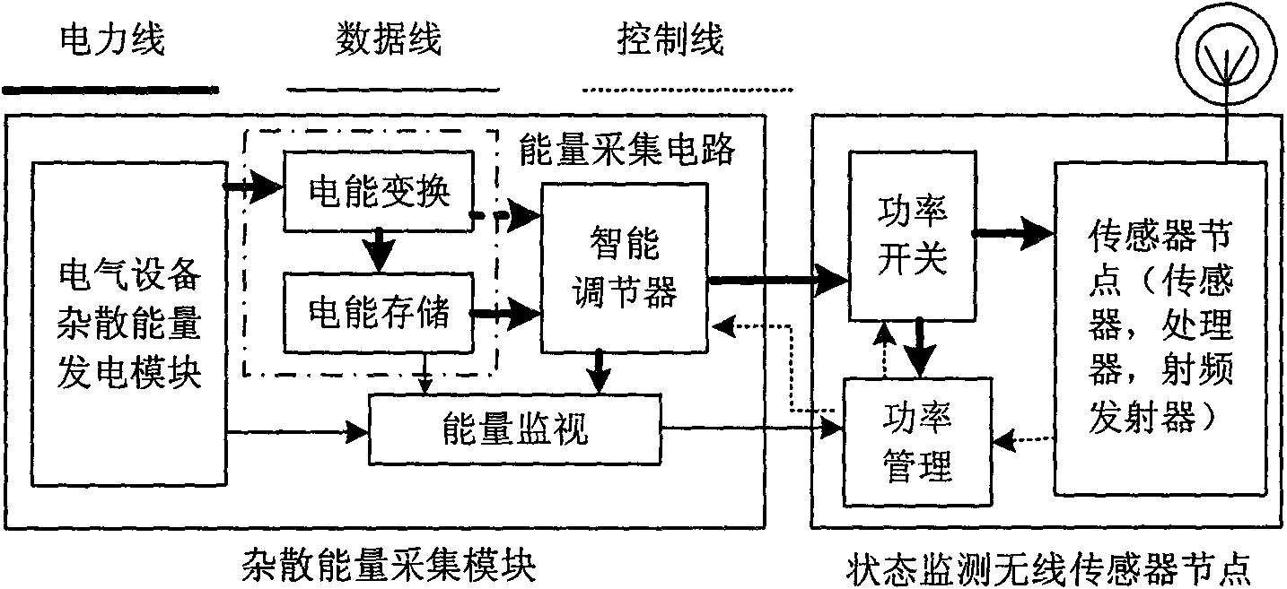
[0032] Embodiment 3 is to collect magnetic leakage energy generated during the operation of electrical equipment to supply power to the wireless sensor system. Different from the previous two embodiments, the energy harvesting coil is used as the energy harvesting device in Embodiment 3. The energy-taking coil is placed in a place where the leakage magnetic field of electrical equipment is relatively concentrated (such as the end of the transformer and reactor coil). Since the leakage magnetic field of electrical equipment is usually relatively strong, and the divergence area is large, and the leakage magnetic field will cause a large loss in the metal structure, therefore, it is necessary to extract the energy of the leakage magnetic field through the energy harvesting coil to supply power to the wireless sensor system. Doable, and it makes a lot of sense.

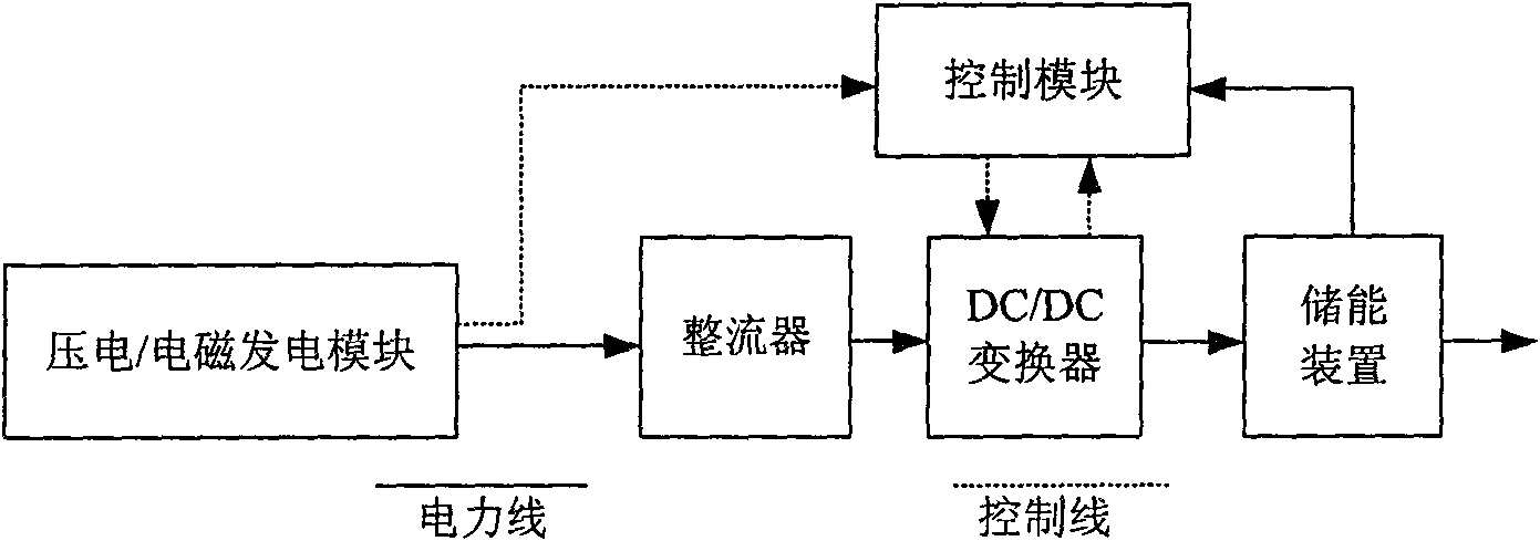
[0033] The leakage magnetic energy generating device is composed of three parts: the energy harvesting coil, the electr...


PUM


Abstract

The invention relates to a stray energy power supplying method of an electrical equipment status monitoring wireless sensing system; a vibration power-generating device, or a temperature difference power-generating device or a flux leakage power-generating deice is adopted to lead mechanical vibration energy or heat energy or flux leakage energy which is generated in the operating process of the electrical equipment to be converted into electrical energy, and the electrical energy is transformed and adjusted by a transformation module, and the transformed electrical energy is stored in an energy storage device such as a rechargeable battery, a capacitor and the like, so as to supply power for the node of the electrical equipment status monitoring wireless sensor. A device applied to the stray energy power supplying method comprises a stray energy power-generating module such as vibration power generation, temperature difference power generation or flux leakage power generation, an electrical energy conversion module and an electrical energy storage module which are arranged on the electrical equipment. The invention can effectively utilize stray energy generated in the operating process of the electrical equipment to supply power for the node of the wireless sensor.

Description

technical field [0001] The invention relates to a method and a device for supplying power to state monitoring wireless sensor nodes by using stray energy generated by electrical equipment during operation. Background technique [0002] In order to improve the service life and reliability of various electrical equipment such as power generation equipment, power transmission and transformation equipment, and electrical equipment (including various electromechanical equipment and household appliances) in the power system, it is very important to monitor the condition of these electrical equipment. meaning. At present, the state monitoring of electrical equipment is powered by traditional power supply (wired mode) or battery (wireless mode). There is no precedent for using stray energy to power the wireless sensor system for electrical equipment status monitoring at home and abroad. The use of traditional power supply requires laying a large number of signal cables, the wiring ...

Claims


Application Information

Patent Timeline
IPC IPC(8): H02N2/18H02N11/00H02K35/00H02J7/00H02J7/02
Inventor 邱清泉肖立业黄天斌郭文勇戴少涛张国民辛守乔
Owner INST OF ELECTRICAL ENG CHINESE ACAD OF SCI
Learn More