Clad copper foil printed circuit board laminating plate of radiator

A technology for printed circuit boards and heat sinks, applied to printed circuit parts, circuits, electrical components, etc., can solve problems such as poor heat dissipation, low heat transfer efficiency, and large thermal resistance of the insulating layer, achieving poor heat dissipation, Large thermal resistance and low heat transfer efficiency

Inactive Publication Date: 2010-02-24
常州市超顺电子技术有限公司 +1
View PDF3 Cites 7 Cited by
  • Summary
  • Abstract
  • Description
  • Claims
  • Application Information

AI Technical Summary

Problems solved by technology

Undoubtedly, its heat dissipation effect is very unsatisfactory
And such as Chinese patent authorization announcement number ① CN201191609Y, ② CN201110471Y and ③ CN2926814Y etc., although all have better heat dissipation performance, but also are easy to understand the main deficiency that they exist: one, the heat dissipation effect is poor
Because the aforementioned ①②③Patent technology is set between the circuit layer (board) and the heat dissipation layer (body) is an insulating layer (board), and the thermal resistance of the insulating layer (board) is large, the heat transfer efficiency is low, so Its heat dissipation effect is poor; especially the aforementioned No. ② patent technology adopts the insulating board assembly method, because there is an assembly gap between related parts, so its heat dissipation effect is even worse; also the aforementioned No. ③ patent technology, due to the circuit board and There is also an isolation layer between the heat sinks, and the heat sink is integrated on the shell, so the heat dissipation effect is even worse; the second is that the structure is unreasonable
The above-mentioned 3 patented technologies are all assembled structures, and the assembled structure will inevitably affect its heat dissipation effect; and the heat-dissipated layer of the aforementioned No. ① patent technology is a copper-aluminum double composite layer; , but it cannot be absolutely seamless after all
Due to the numerous fine depressions on the surface of the copper plate and the aluminum plate, and the difference in flatness between the copper plate and the aluminum plate, a large amount of air must be contained between the connecting surfaces of the copper plate and the aluminum plate, and there is a gas phase between the two. The existence of thermal resistance directly and seriously affects the heat dissipation effect of the heat dissipation layer
Third, poor reliability
The insulating layers (boards) of the aforementioned three patented technologies are not clearly defined as insulating layers with flame-retardant properties, and there is no insulating solder resist layer on the surface of the circuit board, so there may be a short circuit in the circuit, and it may cause a fire.
Fourth, the connection between the circuit layer (board) and the LED light-emitting diode is relatively complicated

Method used


Image

  • Clad copper foil printed circuit board laminating plate of radiator
  • Clad copper foil printed circuit board laminating plate of radiator
  • Clad copper foil printed circuit board laminating plate of radiator

Examples


Embodiment Construction

[0024] The present invention will be further described below through the description of specific embodiments with reference to the accompanying drawings.

[0025] One of the specific implementation modes, as attached Figure 1-8 shown.

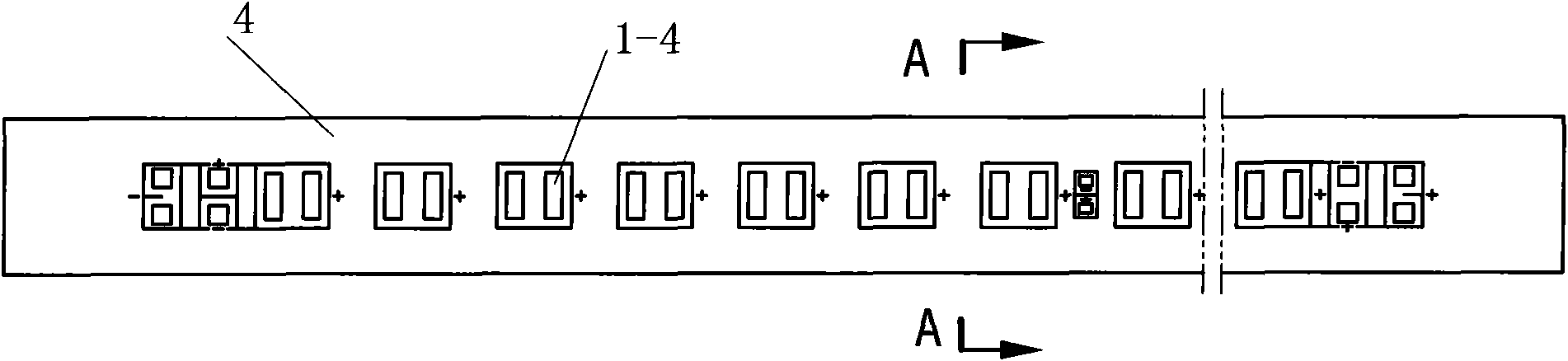
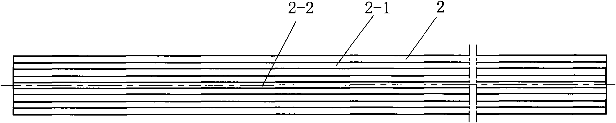
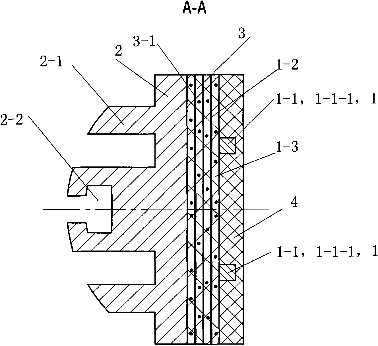
[0026] A radiator-based copper-clad printed circuit board laminate, comprising a plurality of copper-foil printed circuit boards 1 and a radiator 2 provided with several welding pads 1-4 for LED light-emitting diodes, and the radiator 2 It is a substrate; the heat sink 2 is laminated and bonded with the copper foil printed circuit board 1 through the insulating and heat-conducting layer 3; the entire copper foil printed circuit board 1 located outside the pads 1-4 The surface is provided with an insulating solder resist material layer 4 . The copper foil printed circuit board 1 is composed of a copper foil layer 1-1 and a glass fiber cloth 1-2, which are laminated and hot-pressed by a second insulating and heat-conducting layer 1-3; the copp...


PUM


Abstract

The invention discloses a clad copper foil printed circuit board laminating plate of a radiator, comprising a copper foil printed circuit board (1) and a radiator (2). The radiator (2) is used as a base body and (2) is integrally overlapped and bonded with the copper foil printed circuit board (1) into a whole through an insulating heat conducting layer (3); and an insulating solder-resist material layer (4) is arranged on the whole surface of the copper foil printed circuit board (1) located outside a pad (1-4). The invention has the characteristics of reasonable structure, favorable radiating effect, safe and reliable use, and the like.

Description

technical field [0001] The invention relates to a radiator-based copper-clad printed circuit board laminate, in particular to a circuit board laminate with a radiator mainly used for high-power light-emitting diode integrated light-emitting lamps. It belongs to circuit board technology. Background technique [0002] With the in-depth development of energy-saving and consumption-reducing technologies, people have mastered the technology of using light-emitting diodes to integrate light emitters and lighting lamps, and have begun to achieve commercial success. [0003] The key technology for the integration of several light-emitting diodes to produce light emitters and lighting lamps lies in the heat dissipation effect of their circuit boards (substrates). For this reason, existing radiator (body) and circuit board (layer) are come out by the technology of compounding insulating board (layer). The most common is to make aluminum-based copper-clad laminates into printed circu...

Claims


Application Information

Patent Timeline
Patent Type & Authority Applications(China)
IPC IPC(8): H05K1/02H05K7/20H01L33/00F21V29/00
Inventor 邵建良柯建锋
Owner 常州市超顺电子技术有限公司
Why Eureka
Try Eureka