Billet shearing device based on image sensing and shearing method thereof

An image sensor, billet technology

Inactive Publication Date: 2010-03-03
SHANGHAI JIAO TONG UNIV
View PDF0 Cites 18 Cited by
  • Summary
  • Abstract
  • Description
  • Claims
  • Application Information

AI Technical Summary

Problems solved by technology

This document also suffers from complex boundary conditions, large amount of computation, and long time, so it cannot be directly referenced to the online real-time optimal shearing of the head and tail of the billet.

Method used


Image

  • Billet shearing device based on image sensing and shearing method thereof
  • Billet shearing device based on image sensing and shearing method thereof
  • Billet shearing device based on image sensing and shearing method thereof

Examples


Embodiment Construction

[0073] The embodiments of the present invention are described in detail below. This embodiment is implemented on the premise of the technical solution of the present invention, and provides a detailed implementation manner and a specific operation process, but the protection scope of the present invention is not limited to the following implementation. example.

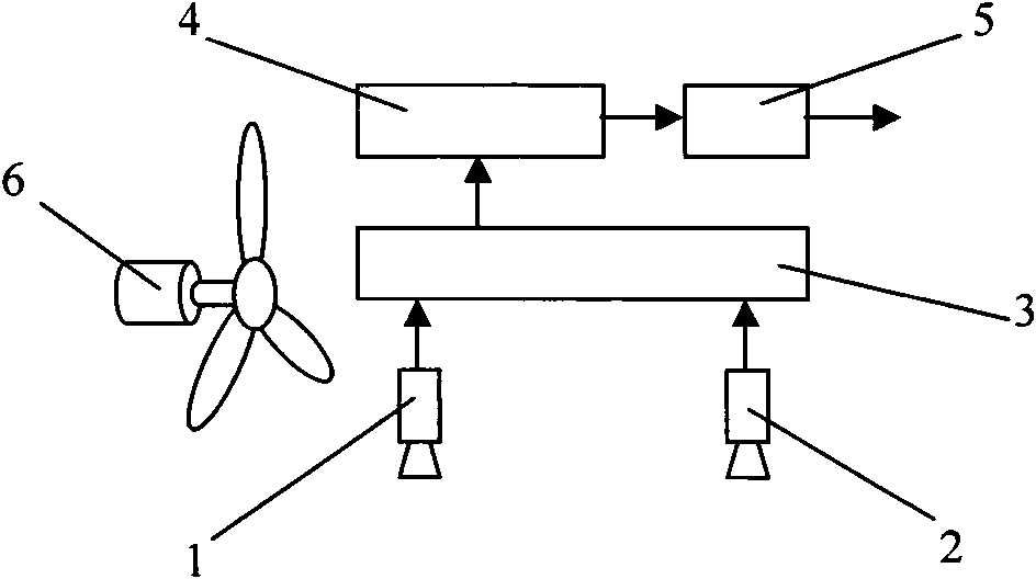
[0074] like figure 1As shown, this embodiment includes: left-eye CCD image sensor 1, right-eye CCD image sensor 2, image processing module 3, image recognition module 4, drive module 5 and cooling mechanism 6, wherein: left-eye CCD image sensor 1 and right-eye CCD image sensor 2. Arranged side by side at the front end 2m of the cutting opening of the thermal bonding shearing machine. The output interfaces of the left-eye CCD image sensor 1 and the right-eye CCD image sensor 2 are connected to the input interface of the image processing module 3, and the output interface of the image processing module 3 is connected to...


PUM


Abstract

The invention provides a billet shearing device based on image sensing and a shearing method thereof. The method comprises the following steps: setting a coordinate system by two CCD image sensors, animage processing module, an image identification module and a drive module; performing image acquisition in real time; extracting a billet contour line, identifying a head part and a tail part of thebillet; determining an optimum shearing lines at the head part and the tail part of the billet, obtaining the distance between the endpoint of the billet head part to be sheared and a shearing edge of a shearing machine, and controlling the shearing time of the shearing machine. In the invention, by adopting image acquisition, image processing and identification calculation in the above steps, the optimum shearing lines at the head part and at the tail part of the billet can be finally identified; and operation of a servo mechanism of the shearing machine can be accurately controlled according to the coordinate information of the optimum shearing lines, thus obtaining the best energy and material conservation effect for shearing the billet on a hot rolling production line.

Description

technical field [0001] The invention relates to a shearing device and a shearing method in the technical field of mechanical equipment, in particular to a billet shearing device and a shearing method based on image sensing. Background technique [0002] Hot continuous rolling and shearing in steel mills is an important part of the continuous rolling process. The purpose is to cut off the curved edges that appear at the head and tail of the billet, so that the overall billet presents an approximately rectangular band. How to realize shear optimization is directly related to the technical problems of saving materials, energy and improving economic efficiency of enterprises. Specifically, it is to solve the optimal shearing problem of the billet head and tail on the hot rolling machine. [0003] After searching the existing technical documents, it was found that the paper "Design and Implementation of the Optimal Cutting Algorithm for Plates" ("Computer Engineering and Applica...

Claims


Application Information

Patent Timeline
Patent Type & Authority Applications(China)
IPC IPC(8): B23D31/00
Inventor 张秀彬应俊豪焦东升钱斐斐
Owner SHANGHAI JIAO TONG UNIV
Why Eureka
Try Eureka