Discharge circuit of electrosparking power supply

A discharge circuit and electric spark technology, applied in the field of power supply, can solve the problems of unfavorable charging and discharging time programmed control, a single tiny pulse cannot provide energy, and the inter-electrode ionization pulse stops for a long time, so as to shorten the deionization time, The effect of shortening the electric field establishment time and improving the processing quality

Inactive Publication Date: 2010-03-03
BEIJING DIAMOND & SPARK SCI & TECH SHARE
View PDF0 Cites 5 Cited by
  • Summary
  • Abstract
  • Description
  • Claims
  • Application Information

AI Technical Summary

Problems solved by technology

[0008] 1. The closing and opening of the selection switch in the explosion-increasing capacitor branch is related to the switching of charging and discharging states and the selection of capacitance value, which is not conducive to independently realizing the programmed control of charging and discharging time;
[0009] 2. When the capacitance value needs to be selected according to the processing conditions, because the capacitance connected to the circuit needs a certain charging time, especially when processing hard alloy or titanium alloy workpieces, the processing efficiency will be affected;
[0010] 3. For large-area precision machining, due to the increase in the electrode area of ​​the workpiece, the inter-electrode capacitance increases, and the single tiny pulse provided by the discharge cannot provide enough energy, resulting in the accumulation of several pulse energies to complete a discharge. The processing efficiency Low;
[0011] 4. For large-area precision machining, due to the limited energy provided by the power supply within a working pulse cycle, it is difficult to accurately control the ability of each processing point, and the surface quality is poor;
[0012] 5. The ability of the deionization circuit is poor. If the selected deionization resistance is too small, the voltage drop between the electrode and the workpiece will be too large. On the contrary, if the resistance is too large, the deionization speed will be too slow, that is, the deionization pulse between electrodes will stop. Some parts take a long time and affect the processing efficiency;
[0013] 6. The electric field establishment process takes a long time, and the rising edge of the voltage waveform and current waveform in the discharge waveform cannot reach the ideal state and is steep enough, and the efficiency of EDM is low.

Method used


Image

  • Discharge circuit of electrosparking power supply
  • Discharge circuit of electrosparking power supply

Examples


Embodiment Construction

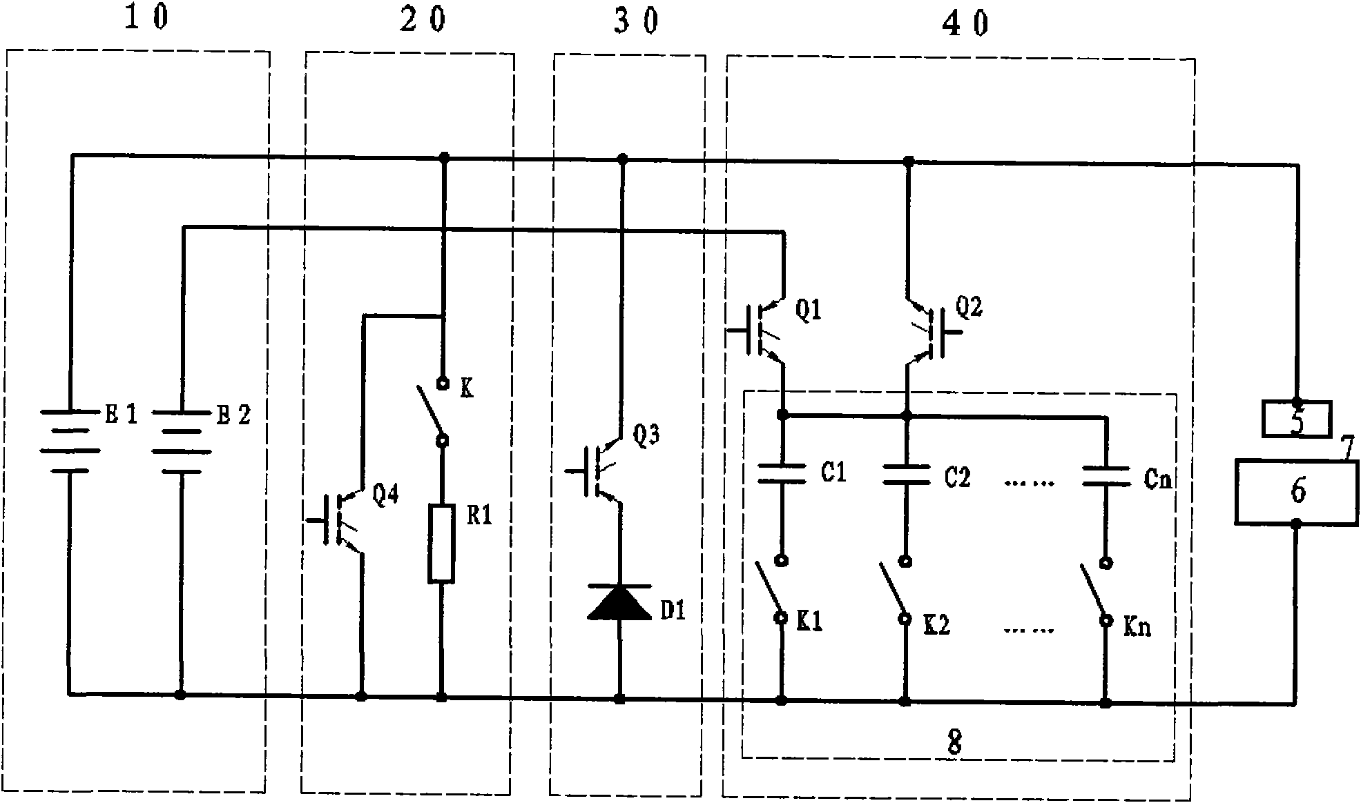
[0035] figure 2 Shown is the principle schematic diagram of the discharge circuit structure of the electric discharge machining power supply of the present invention, the discharge circuit includes a power supply 1 composed of a working power supply E1 and a charging power supply E2, and a discharge branch circuit composed of an electrode 5 and a connecting terminal of a workpiece 6, It also includes a deionization branch 20, a negative wave absorption branch 30 and an explosion-increasing capacitor branch 40 respectively connected in parallel with the discharge branch, the electrode end of the discharge branch is connected to the positive output terminal of the working power supply E1, The workpiece connection terminal is connected to the negative output terminal of the working power supply E1.

[0036] Wherein, the explosion-increasing capacitor branch is composed of a capacitive unit 8 and a capacitor discharge switch Q2 connected in series, one end of the capacitor discha...


PUM


Abstract

The invention relates to a discharge circuit of an electrosparking power supply. The discharge circuit comprises a working power supply, a charge power supply and a discharge circuit branch consistingof an electrode and a connection terminal of a workpiece, and also comprises a deionization circuit branch, a negative wave absorption circuit branch and an exploding capacitor circuit branch, wherein an electrode end of the discharge circuit branch is connected with a positive output end of the working power supply, the connection terminal of the workpiece is connected with a negative output endof the working power supply, and the exploding capacitor circuit branch consists of a capacitive unit and a capacitor discharge switch that are connected in series, the capacitor discharge switch anda capacitor charge switch are both a power field effect transistor or an insulated-gate bipolar transistor, and an electronic switch is a power field effect transistor or an insulated-gate bipolar transistor. The discharge circuit can immensely shorten the setup time of an electric field, and improve processing time, simultaneously the quality of processed surface and also the deionization capacity.

Description

technical field [0001] The invention relates to a power supply which can improve the speed and performance of electric discharge machining (EDM), in particular to a discharge circuit of the electric discharge machining power supply which can improve the speed and performance of finishing machining. Background technique [0002] At present, the circuit structure of the discharge circuit of the processing power supply commonly equipped on general-purpose EDM machine tools is as follows: figure 1 As shown, it includes a working power supply (E) 1 and a discharge branch composed of the connection terminals of the electrode 5 and the workpiece 6, and also includes a deionization branch 2, a negative wave absorption branch 3 and a negative wave absorption branch respectively connected in parallel with the discharge branch. The explosion-increasing capacitor branch 4 and the workpiece connection terminal are used for installing the workpiece and electrically connecting with the wor...

Claims


Application Information

Patent Timeline
Patent Type & Authority Applications(China)
IPC IPC(8): B23H1/02
Inventor 罗培刚
Owner BEIJING DIAMOND & SPARK SCI & TECH SHARE
Why Eureka
Try Eureka