Millimeter-wave quasi-optical integrated dielectric lens antenna and array thereof

A dielectric lens antenna, dielectric lens technology, applied to antenna arrays, antennas, electrical components, etc., can solve the problems of slow scanning speed of mechanical transmission, high price, small size of horn antenna structure, etc., and achieve strong dust-proof and anti-pollution performance, Robust structure and mechanical properties, low cost of mass production

Inactive Publication Date: 2010-03-03
阮树成
View PDF0 Cites 257 Cited by
  • Summary
  • Abstract
  • Description
  • Claims
  • Application Information

AI Technical Summary

Problems solved by technology

[0002] Horn radiation antennas, parabolic reflective Cassegrain antennas, and microstrip antennas are commonly used in millimeter-wave communication and radar antennas. Horn antennas in the high-end frequency bands of millimeter waves are relatively small in size, difficult to manufacture, and expensive
Moreover, the feeding parabolic reflective Kag antenna tracks the maneuvering target, the scanning speed of the mechanical transmission is slow, the accuracy is poor, and the failure rate is high in harsh environments, such as the anti-collision radar equipped in the car, which is dusty, strong vibration, and large temperature difference , the antenna sensor is required to have extremely high environmental adaptability, just like the "eyes" must see all kinds of situations on the road in a complex environment at all times, and avoid collisions in real time
In addition, due to the short working wavelength of the millimeter-wave microstrip antenna, the small size of the feed element, and the large dielectric loss of the substrate, it is difficult to obtain the directivity of the narrow beam of the high-gain antenna by simply using the microwave microstrip antenna technology structure.

Method used


Image

  • Millimeter-wave quasi-optical integrated dielectric lens antenna and array thereof
  • Millimeter-wave quasi-optical integrated dielectric lens antenna and array thereof
  • Millimeter-wave quasi-optical integrated dielectric lens antenna and array thereof

Examples


Embodiment Construction

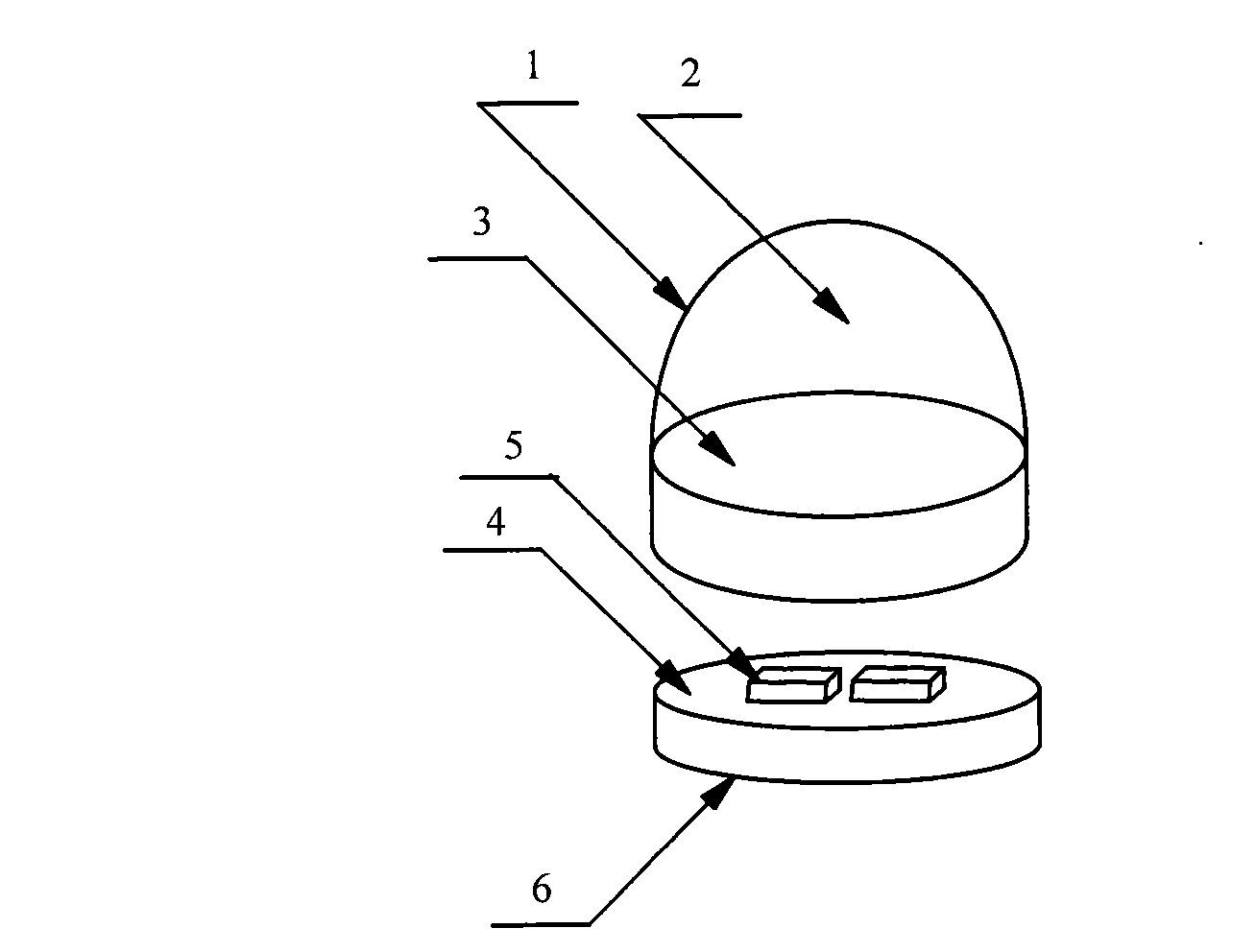
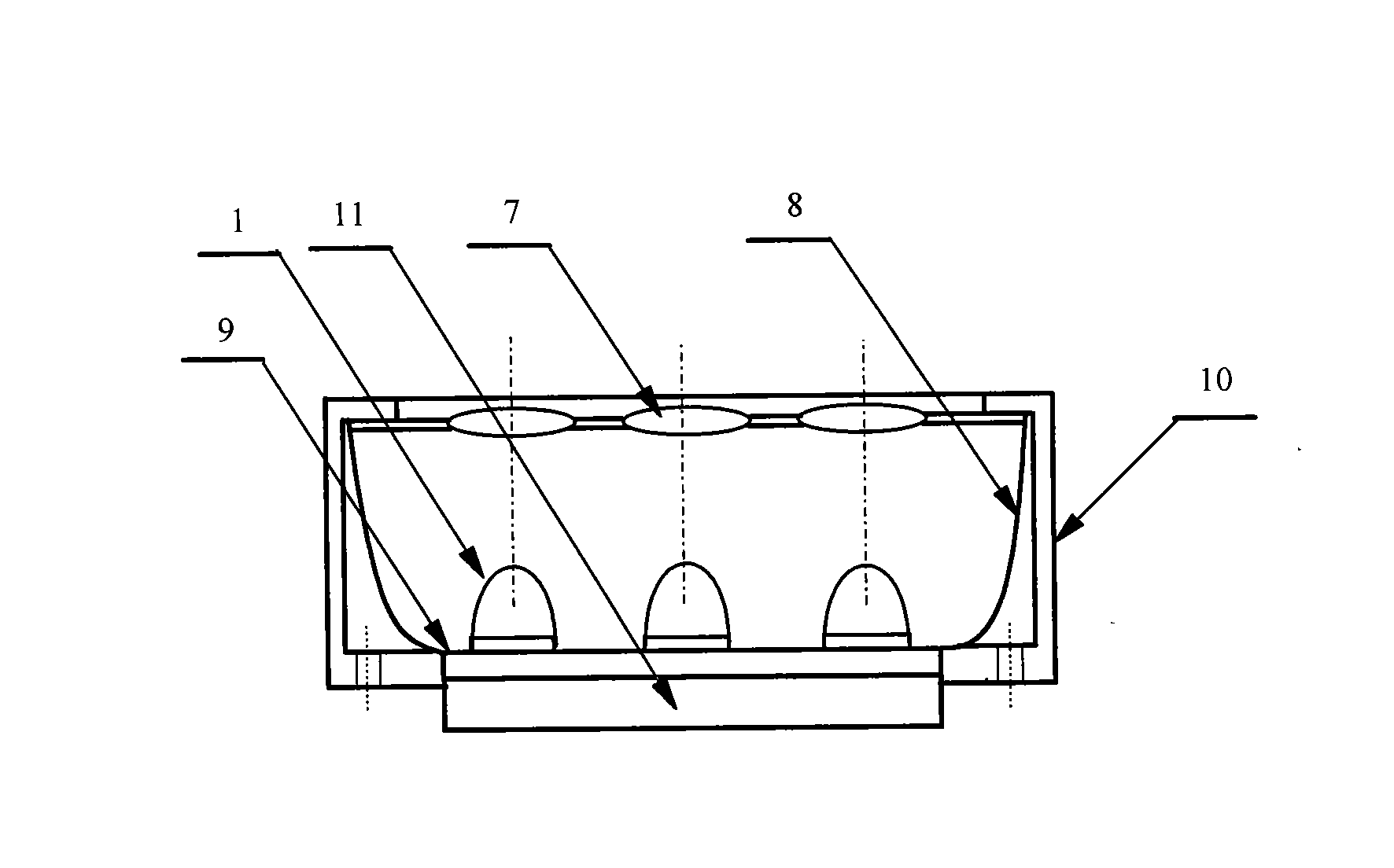
[0013] refer to figure 1 , figure 2 , the specific implementation method and embodiment of the present invention are composed of microstrip integrated antenna 5, dielectric lens 1, objective lens 7, array base 9, reflector 8, protective cover 10, beam switching switch 11, and one end face of dielectric lens 1 is a hemisphere Or ellipsoid 2, the other end face is a cylinder 3 section, the microstrip integrated antenna 5 is generated by a double-sided metal layer dielectric substrate 4, and its front is at least composed of a single microstrip patch feed element or double dipole oscillator or logarithmic The vibrator or spiral vibrator is the feed element, which is tightly glued to the dielectric lens 1. The cross section of the cylinder 3 is the feed source, the metal layer 6 on the back is grounded, the end surface of the hemisphere or ellipsoid 2 of the dielectric lens 1 is the antenna radiation surface, and the cylindrical body of the dielectric lens 1 The length of the bo...


PUM


Abstract

The invention relates to the technical field of radar, in particular to a millimeter-wave quasi-optical integrated dielectric lens antenna and an array thereof. The array consists of a microstrip integrated antenna, a dielectric lens, an objective lens, an array base, a reflecting mirror, a protective cover and a beam transfer switch; one end face of the dielectric lens is a hemisphere or an ellipsoid, while the other end face is a cylindrical section; the microstrip integrated antenna is generated by an dielectric substrate, the front surface of the dielectric substrate is closely adhered tothe cylindrical section of the dielectric lens and serves as a feed source, and the back surface is grounded; the hemispherical or ellipsoidal end face of the dielectric lens is an antenna radiating surface; the length of the cylindrical part of the dielectric lens can be changed; the antenna array is arranged into a linear array or an area array; the array base and the reflecting mirror have conical quasi-optical reflecting mirror surfaces; the focus of the objective lens of the linear array or the area array aligns with the central line of the dielectric lens; the protective cover is arranged outside; and the antenna array is controlled by the beam transfer switch. The antenna structure has strong shock resistance and dust prevention, and is suitable for millimeter-wave radars for planes, automobiles and ships, and receiving/emitting sensing of communication equipment.

Description

technical field [0001] The invention relates to the technical field of communication and radar antennas, in particular to a millimeter-wave quasi-optical integrated dielectric lens antenna and an array thereof. Background technique [0002] Horn radiation antennas, parabolic reflective Cassegrain antennas, and microstrip antennas are commonly used in millimeter-wave communication and radar antennas. Horn antennas in the high-end frequency bands of millimeter waves are relatively small in size, difficult to manufacture, and expensive. Moreover, the feeding parabolic reflective Kag antenna tracks the maneuvering target, the scanning speed of the mechanical transmission is slow, the accuracy is poor, and the failure rate is high in harsh environments, such as the anti-collision radar equipped in the car, which is dusty, strong vibration, and large temperature difference , requiring the antenna sensor to have extremely high environmental adaptability, just like the "eyes" must s...

Claims


Application Information

Patent Timeline
Patent Type & Authority Applications(China)
IPC IPC(8): H01Q15/08H01Q19/06H01Q21/00H01Q23/00
Inventor 阮树成
Owner 阮树成
Why Eureka
Try Eureka