Extruding device of porous hard alloy profile

A technology of hard alloy and extrusion device, which is applied in the direction of metal extrusion, metal extrusion die, metal extrusion control equipment, etc. It can solve the problems of short profile length, large hole size, and air holes, etc., and achieve load reduction , Reduce extrusion resistance, good mechanical properties

Inactive Publication Date: 2010-03-10
FUJIAN JINXIN TUNGSTEN
View PDF2 Cites 11 Cited by
  • Summary
  • Abstract
  • Description
  • Claims
  • Application Information

AI Technical Summary

Problems solved by technology

[0005] The object of the present invention is to provide a kind of cemented carbide profile extruding device with holes, the length of the cemented carbide profile extruded by this device and the diameter of the inner hole are not limited, and the extrusion process is completed in a vacuum state to ensure extrusion The internal quality of the parts is good, which solves the problems of short profile length, large hole size, and internal pore defects in the extrusion molding of high-performance cemented carbide with holes.

Method used


Image

  • Extruding device of porous hard alloy profile
  • Extruding device of porous hard alloy profile
  • Extruding device of porous hard alloy profile

Examples


Embodiment 1

[0039] Example 1: Extrusion of Φ14mm×Φ1.5mm×300mm single-hole alloy rod

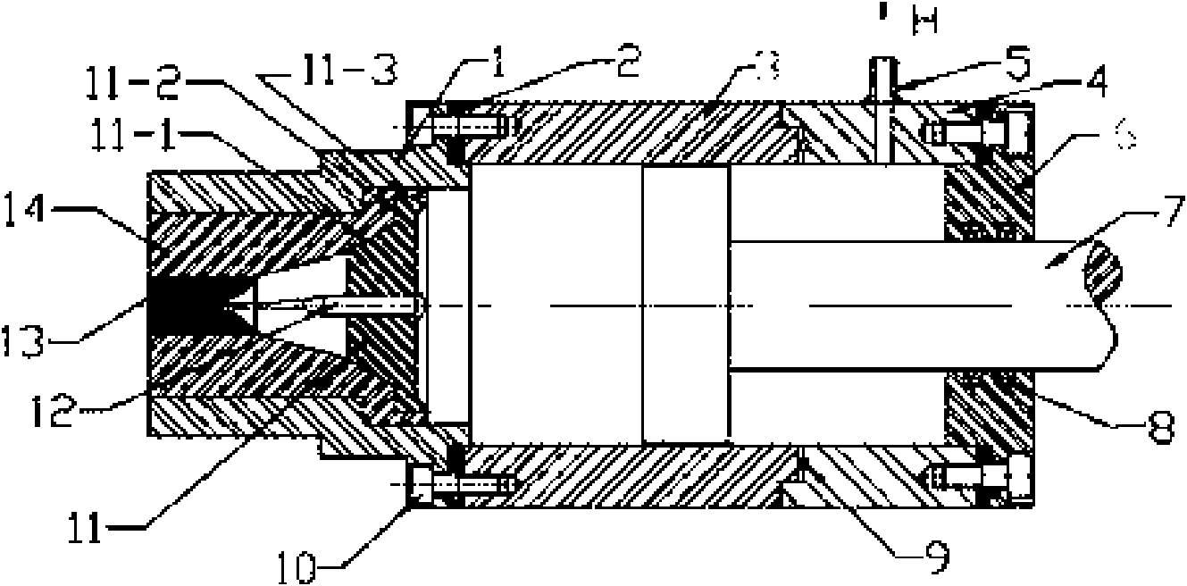
[0040] The perforated cemented carbide profile extrusion device of the present invention operates according to the workflow of mold loading, material loading, vacuuming, and extrusion:

[0041] (1) Design and manufacture the mold, core rod and core rod support according to the outer circle and inner hole size of the alloy round rod, and grind the working surface of the above workpiece to a mirror surface; then install the mold formwork according to the steps.

[0042] (2) Use an adhesive tape to seal the mold outlet; withdraw the extrusion push rod; move out the front press cylinder 3 and lift the charging port upwards, pour alloy powder into the front press cylinder; put the press cylinder and extrusion Press the push rod to reset.

[0043] (3) Vacuumize to make the vacuum degree of the inner cavity of the cylinder reach 70Pa~80Pa.

[0044] (4) Start the machine and squeeze the alloy powder out of the m...

Embodiment 2

[0045] Example 2: Extrusion of Φ14mm×Φ1.5mm×300mm double-hole alloy round rod

[0046] The extrusion operation steps and the vacuum degree of the inner cavity of the press cylinder are consistent with the first embodiment.

[0047] The extrusion die used the mold of Example 1. When making mandrels, two mandrels were manufactured by splitting and placed on the mandrel support seat, and the mandrel support was manufactured according to the size of the mandrel support. The finish of the working surface is still mirror-like.

[0048] Install the mold according to the mold loading steps, operate according to the technological process of embodiment 1, and successfully extrude a Φ14mm×Φ1.5mm×300mm double-hole alloy round rod.

Embodiment 3

[0049] Example 3: Extrusion of 8mm×8mm×Φ1.0mm×300mm square single-hole profile

[0050] The extrusion operation steps and the vacuum degree of the inner cavity of the press cylinder are consistent with the first embodiment.

[0051] When making the mould, plan the size of the square cavity and mandrel according to the process parameters, and grind the working surfaces of the mold and mandrel to a mirror surface. Install the mold according to the mold loading steps, operate according to the technological process of the first embodiment, and successfully extrude the 8mm×8mm×Φ1.0mm×300mm square single-hole profile.


PUM


Abstract

The invention discloses an extruding device of a porous hard alloy profile. A mold system thereof consists of a core rod bracket (11), an extrusion core rod (12), a mold (13) and a mold sleeve (14), which are movably assembled in a die set (1); a pressing cylinder system comprises a front pressing cylinder (3), a rear pressing cylinder (4), an extrusion pushing rod (7) and a rear end cover (6), wherein the rear pressing cylinder (4) is provided with an air vent; an air exhaust opening (5) above the air vent is coupled with a vacuumizing system; the extrusion pushing rod (7) passes through therear end cover to be connected with a hydraulic system; and the die set (1), the front pressing cylinder (3), the rear pressing cylinder (4) and the rear end cover (6) realize sealing connection by fastening screws and a pull rod mechanism so as to form an extrusion device body. The length of the hard alloy profile and the hole diameter of the inner hole, extruded by the device, are not limited, the extrusion process is ensured under vacuum state to ensure good internal quality of an extruding part, and the difficulties that the existing porous high-performance hard alloy has short profile length, large size of the hole diameter, and air holes in the inner part when being extruded and molded are solved.

Description

1. Technical field [0001] The invention relates to extrusion forming equipment for mechanical processing, in particular to an extrusion device for hard alloy profiles with holes. 2. Background technology [0002] Since cemented carbide cutting tools are expensive, how to improve their service life is an important issue in the industry. A cooling hole is added to the center of the cemented carbide integral tool, and the coolant is passed through to cool the tool during machining, which can effectively reduce the cutting heat of the tool and the workpiece in a timely and effective manner, reduce the thermal expansion of the tool and the workpiece, and reduce the wear of the tool. While improving the machining accuracy of the workpiece, the service life of the tool is extended. The preparation of cemented carbide tools with holes is currently made by machining alloy profile compacts. This preparation method limits the length of the profile and thus the length of the tool, whic...

Claims


Application Information

Patent Timeline
IPC IPC(8): B21C23/21B21C25/02B21C31/00
Inventor 张寿德丁华堂张阳生
Owner FUJIAN JINXIN TUNGSTEN
Why Eureka
Try Eureka