
Coated abrasive grinder of propeller blade

A belt grinder and propeller technology, applied in the direction of belt grinder, grinding machine, grinding/polishing equipment, etc., can solve the problems of poor processing accuracy, low processing efficiency, and difficult to guarantee the quality of the profile, so as to reduce management and production costs , Improve the qualified rate of finished products and reduce the effect of labor intensity

Inactive Publication Date: 2011-06-22
CHONGQING SAMHIDA GRINDING MACHINE
View PDF0 Cites 2 Cited by
  • Summary
  • Abstract
  • Description
  • Claims
  • Application Information

AI Technical Summary

Problems solved by technology

Although manual grinding can realize the grinding and polishing of complex curved surfaces, due to the subjective influence of people, the quality of the curved surface surface is determined by the proficiency of the operator, so it is impossible to effectively control the dimensional accuracy of the workpiece, resulting in poor processing accuracy, The quality of the surface is difficult to guarantee, and even the grinding thickness is uneven in the surface polishing, and the product consistency is difficult to guarantee; at the same time, the labor intensity of the workers is high, the processing efficiency is low, the working environment of the production personnel is harsh, and the management cost is high.
[0004] In order to solve the above problems, a professional blade grinding machine tool appeared, which greatly improved the grinding efficiency of the blade, but the rotating support arm of the existing equipment grinding head is too long, the rigidity is poor, and it cannot adapt to the large feed of the blade profile There is also a structure that realizes the automatic grinding and polishing of workpieces with complex shapes through the mechanical arm, which can improve work efficiency and yield. However, because the equipment adopts a series manipulator structure, the rigidity of the equipment is also very poor, and it cannot adapt to large-scale Functional Requirements for Rapid Blade Grinding

Method used


Image

  • Coated abrasive grinder of propeller blade
  • Coated abrasive grinder of propeller blade
  • Coated abrasive grinder of propeller blade

Examples


Embodiment Construction

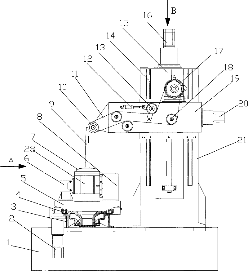
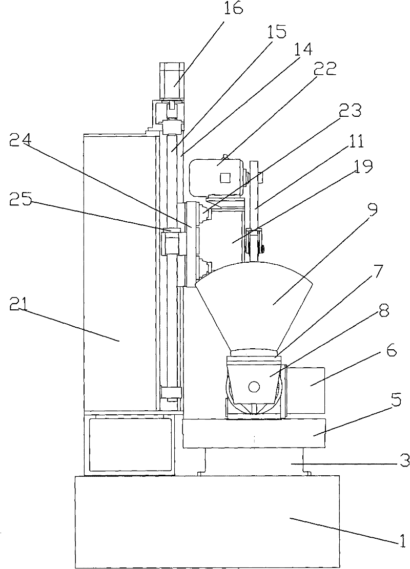
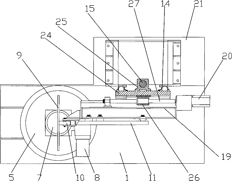
[0024] figure 1 It is a schematic diagram of the structure of the present invention, figure 2 for figure 1 View along direction A, image 3 for figure 2 View along the B direction, as shown in the figure: the propeller blade abrasive belt grinder of this embodiment includes a bed 1, a grinding head mechanism, a grinding head feeding mechanism, a workpiece orientation adjustment mechanism and an automatic control system;

[0025] Grinding head mechanism comprises abrasive belt 11, driving wheel 17, contact wheel 10, tensioning wheel 13 and grinding head driving motor 22, and described abrasive belt 11 walks around driving wheel 17 and contacting wheel 10 and is tensioned by tensioning wheel 13, The power output shaft of the grinding head drive motor 22 is in transmission cooperation with the drive wheel 17;

[0026] The grinding head feeding mechanism includes an axial feeding mechanism and a radial feeding mechanism relative to the workpiece, and the radial feeding mecha...


PUM


Abstract

The invention discloses a coated abrasive grinder of a propeller blade, which comprises a grinder body, a grinding head mechanism, a grinding head feeding mechanism and a workpiece position adjusting mechaism, wherein the grinding head mechanism comprises an abrasive belt, a driving wheel, a contact wheel, a tensioning wheel and a grinding head drive motor; the grinding head feeding mechanism comprises an axial feed mechanism and radial feed mechanism relative to the workpiece; the coated abrasive grinder realizes combination of four degree of freedom of space by reasonable distribution of grinding head feeding and adjustment of the angle of the workpiece position as well as a shorter drive chain, guarantees the rigidity of the grinding head mechanism and a workpiece clamping mechanism, ensures the contact stabiltiy between the contact wheel and the workpice when the contact wheel rotates with a high speed, and improves work efficiency simultaneously when guaranteeing the process sizeprecision of a complex curve workpiece; and thickness is even in curve polishing, the quality of profiles is ensured, the qualificaiton rate of finished products is improved, the labor intensity of workers is reduced, and the management and production cost is decreased.

Description

technical field [0001] The invention relates to an abrasive belt grinder, in particular to a propeller blade abrasive belt grinder. Background technique [0002] A belt grinder is a grinding machine that uses a fast-moving abrasive belt as an abrasive tool for grinding and polishing. With the rapid development of grinding machine technology, abrasive belt grinding machines have developed into high-efficiency and low-power finishing equipment. Especially in the processing of large-size plates, bars and complex profiles, its advantages are particularly obvious. The abrasive belt grinder is driven by the drive wheel to move the abrasive belt, and the tension wheel is used to tension the abrasive belt. The back pressure is provided by the contact wheel or the support plate to generate contact pressure on the workpiece and form a cutting angle to complete the grinding process of the workpiece. [0003] Due to the limitation of the structure of the grinding machine and the insta...

Claims


Application Information

Patent Timeline
Patent Type & Authority Patents(China)
IPC IPC(8): B24B21/16B24B21/18B24B21/20
Inventor 黄云杨俊峰刘荔黄智刘瑞杰
Owner CHONGQING SAMHIDA GRINDING MACHINE
Learn More