Material loading system for producing marsh gas by utilizing straw fermentation

A straw and feeding technology, which is applied in the field of feeding system, can solve the problems of easy falling behind, blockage of pipelines, affecting the gas production of the digester, etc., and achieve the effect of preventing blockage, ensuring raw materials and ensuring output.

Inactive Publication Date: 2010-03-10
HENAN FUCHENG ECOLOGICAL ENERGY TECH
View PDF0 Cites 7 Cited by
  • Summary
  • Abstract
  • Description
  • Claims
  • Application Information

AI Technical Summary

Problems solved by technology

[0003] A complete large and medium-sized biogas fermentation project, regardless of its size, includes the following technological process: collection of raw materials, pretreatment, digester (digester), post-treatment of discharged materials, purification and storage of biogas, etc. Currently, After the pretreatment, the raw materials are sent to the digester (digester) through the conveying device for fermentation to generate biogas. The generated biogas is filtered and purified for people's daily production and life use or storage. During the transportation of the pretreated raw materials, because Raw materials are generally crop stalks, poultry and livestock manure, etc. These materials are relatively light, and they often float on the surface of the wastewater during the pretreatment process with the wastewater. During the transportation process, traditional pressure pumps and other feeding measures are used. The liquid is always pumped up first, and the straw and other raw materials are easy to fall behind, which is easy to cause blockage of the pipeline, and also affects the gas production of the digester (digester)

Method used


Image

  • Material loading system for producing marsh gas by utilizing straw fermentation

Examples


Embodiment Construction

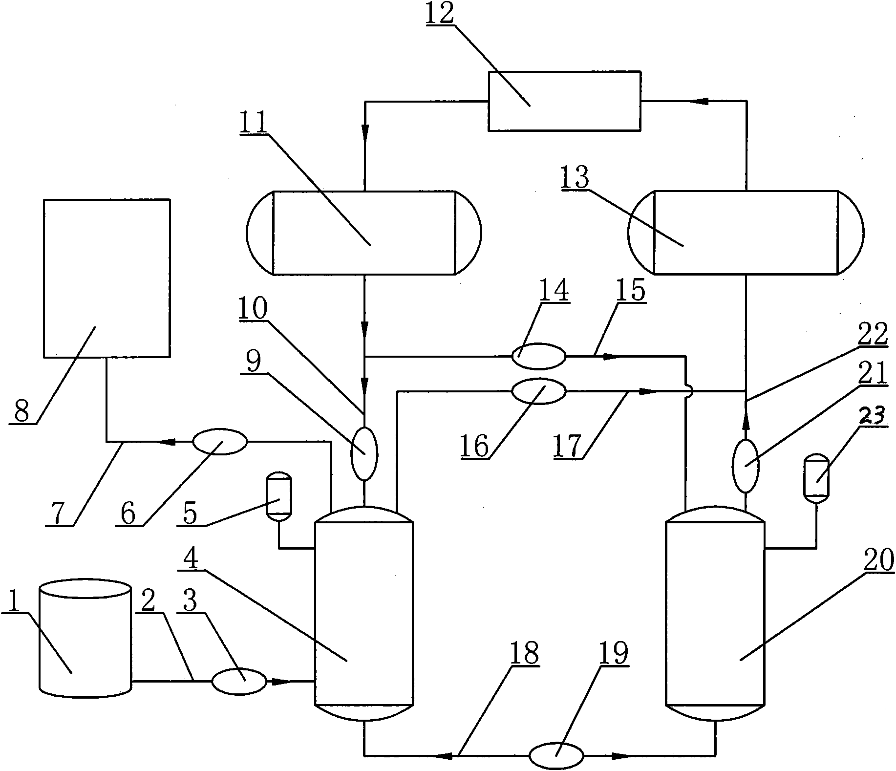
[0012] The present invention will be further described in detail below in conjunction with the accompanying drawings.

[0013] Such as figure 1 As shown, the feeding tank 4 is connected to the straw mixing pool 1 through a pipeline 2, and the pipeline 2 is provided with a valve 3, and the feeding tank 4 is connected to the anaerobic digester 8 through a pipeline 7, and the pipeline 7 is provided with a valve 6. Tank 4 is connected with positive pressure tank 11 through pipeline 10, and pipeline 10 is provided with valve 9, and feeding tank 4 is connected with negative pressure tank 13 through pipeline 17, and pipeline 17 is provided with valve 16, and feeding tank 4 is connected with pipeline 18 and The feeding auxiliary tank 20 is connected, the pipeline 18 is provided with a valve 19, the feeding auxiliary tank 20 is connected with the positive pressure tank 11 through the pipeline 15, the pipeline 15 is provided with a valve 14, the feeding auxiliary tank 20 and the negativ...


PUM


Abstract

The invention relates to a material loading system for producing marsh gas by utilizing straw fermentation, belonging to the technical field of marsh gas generation. The invention comprises a materialloading bucket, a material loading auxiliary bucket, a positive pressure bucket, a negative pressure bucket and an air compressor; the material loading bucket and a straw agitating tank are connectedvia a pipeline which is provided with a valve; the material loading bucket and an anaerobic digester via a pipeline which is provided with a valve; the material loading bucket and the positive pressure bucket via a pipeline which is provided with a valve; the material loading bucket and the negative pressure bucket via a pipeline which is provided with a valve; the material loading bucket and thematerial loading auxiliary bucket via a pipeline which is provided with a valve; the material loading auxiliary bucket and the positive pressure bucket via a pipeline which is provided with a valve;the material loading auxiliary bucket and the negative pressure bucket via a pipeline which is provided with a valve; and the positive pressure bucket and the negative pressure bucket are respectivelyconnected with the air compressor. The invention can effectively avoiding straws from blocking in the pipelines, can adequately convey the raw materials into the anaerobic digester, and ensures the raw materials in the anaerobic digester to be sufficient so as to warrant yield of marsh gas.

Description

Technical field: [0001] The invention belongs to the technical field of biogas generation, and in particular relates to a feeding system for producing biogas by fermenting straw. Background technique: [0002] Biogas, its main component is methane, methane is an ideal gas fuel, it is colorless and odorless, and it can burn when mixed with an appropriate amount of air. The calorific value of pure methane per cubic meter is 34,000 kilojoules, and the calorific value of biogas per cubic meter is about 20,800-23,600 kilojoules. That is, after 1 cubic meter of biogas is completely burned, it can produce the heat equivalent to 0.7 kg of anthracite. Compared with other gases, it has better antiknock performance and is a good clean fuel. In addition to being directly burned for cooking, drying agricultural and sideline products, heating, lighting, and gas welding, biogas can also be used as fuel for internal combustion engines and for the production of chemical raw materials such ...

Claims


Application Information

Patent Timeline
Patent Type & Authority Applications(China)
IPC IPC(8): C12M1/107
CPCC12M21/04Y02E50/343C12M23/58Y02E50/30
Inventor 何贵新何贵忠申云刘堂
Owner HENAN FUCHENG ECOLOGICAL ENERGY TECH
Why Eureka
Try Eureka