Eureka AIR delivers breakthrough ideas for toughest innovation challenges, trusted by R&D personnel around the world.

Plasma display panel

A display panel and plasma technology, applied in the direction of AC plasma display panel, gas discharge electrode, cathode ray/electron beam tube shell/container, etc., can solve the problems of longer sealing processing time, high price, and rising cost. Achieve the effects of shortening the processing time, preventing decomposition, and preventing the reduction of purity

Inactive Publication Date: 2010-03-10
ULVAC INC
View PDF4 Cites 0 Cited by
  • Summary
  • Abstract
  • Description
  • Claims
  • Application Information

AI Technical Summary

Problems solved by technology

However, since the sealing force (adhesion force) is determined by the characteristics and area of ​​the material, a large amount of low-melting-point metal material is required, and in particular, since indium is a rare metal, it is expensive, resulting in an increase in cost
In addition, there is a problem that the time required for the sealing process becomes longer.

Method used


Image

  • Plasma display panel
  • Plasma display panel
  • Plasma display panel

Examples


Embodiment 1

[0108] Ne-4% Xe is used as the discharge gas, and it is introduced into the light-emitting area 15 under a pressure of 400 Torr, and the sealed plasma display panel 10 of the present invention is placed in a constant temperature and humidity chamber at 85°C and a humidity of 95%, and Measure the drop change in discharge voltage. exist Figure 6 (a) shows the relationship between the standing time and the discharge voltage.

[0109] For comparison, under the same conditions, the existing plasma display panel 110 ( Figure 11 ) discharge voltage. exist Figure 6 (b) shows the relationship between the standing time and the discharge voltage.

[0110] The final cell lighting voltage is the driving voltage required to start discharging all cells.

[0111] In addition, the first cell light-off voltage is the voltage for the first cell light-off when the driving voltage is gradually decreased from the state where all the cells are turned on.

[0112] In the plasma display panel ...

Embodiment 2

[0116] Next, the plasma display panel 10 of the present invention was placed in a constant temperature and humidity chamber at 50° C. and a humidity of 50%, and placed in a state where a voltage was applied to the electrodes to emit light, and the discharge voltage was measured. Figure 7 (a) shows the relationship between the time for applying a voltage to the electrode (aging time) and the discharge voltage.

[0117] For comparison, under the same conditions, the existing plasma display panel 110 ( Figure 11 ) discharge voltage. Figure 7 (b) shows the relationship between aging time and discharge voltage.

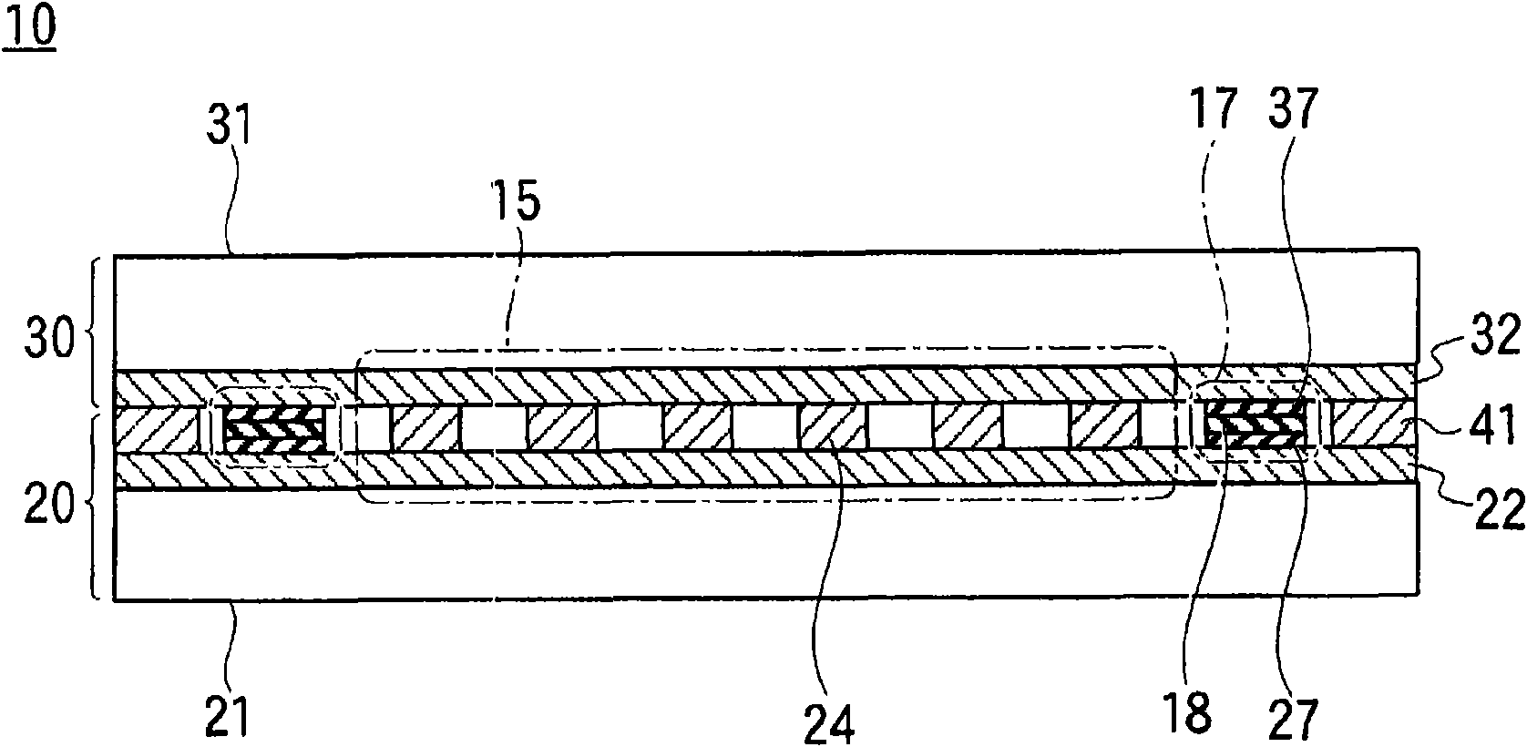
[0118] In the plasma display panel 10 of the present invention, even if the aging time reaches 2000 hours, the voltage rise is 10 V or less. This is because the ultraviolet rays emitted by the plasma are blocked by the sealing portion 17 and do not irradiate the sealing portion 41 , the sealing portion 41 is not decomposed, and the release of impurity gas is prevented....


PUM


Abstract

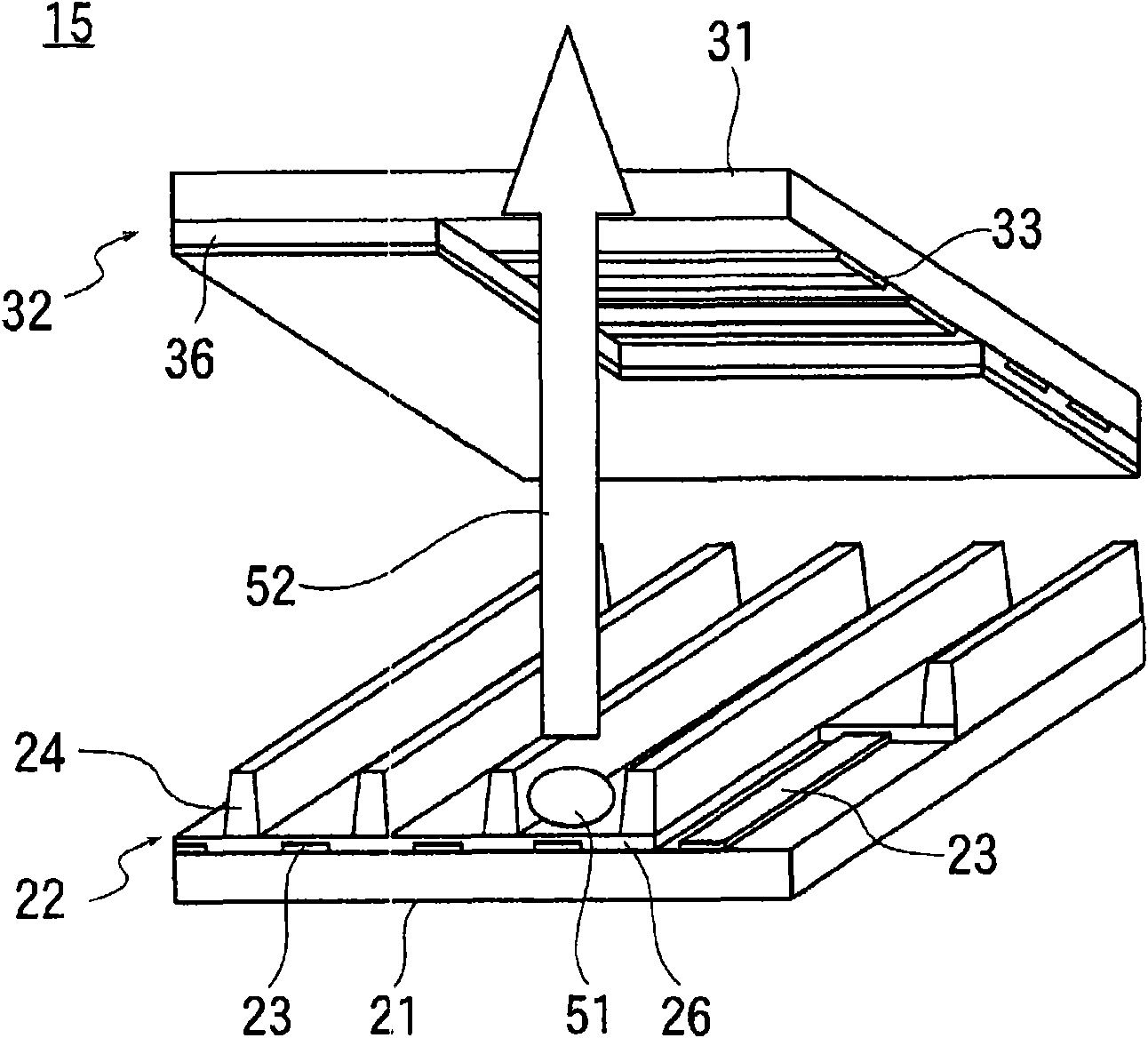
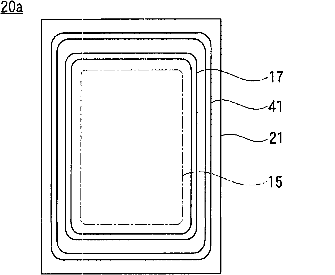
A technique is provided for preventing impurity gas from entering the plasma display panel. A light emitting region 15 is surrounded by a hermetically-sealed part 17 including a metal film tightly adhering to first and second panels 20 and 30, and a sealing part 41 fixing the first and second panels 20 and 30 to each other is located outside the hermetically-sealed part 17. Even when moisture is transmitted through the sealing part 41, the moisture cannot be transmitted through the hermetically-sealed part 17 and does not enter the light emitting region 15. Since the sealing part 41 may transmit the moisture, it can use an ultraviolet curable type resin for improving working efficiency.

Description

technical field [0001] The present invention relates to the technical field of plasma display panels, and in particular, relates to the technology of preventing impurity gas from intruding into the plasma display panel. Background technique [0002] Currently, PDPs are widely used in the field of display devices, and recently, large-screen, high-quality, and low-priced PDPs are required. [0003] At present, the mainstream of PDP is formed by bonding the first panel (rear panel) on which the address electrodes are formed on the glass substrate and the second panel (front panel) on which the sustain electrodes and scan electrodes are formed on the glass substrate. Three-electrode surface discharge type. [0004] Figure 11 Reference numeral 110 in (a) and (b) is a conventional plasma display panel, which has first and second panels 120 and 130 . Figure 11 (a) is a floor plan illustrating the interior, Figure 11 (b) is a cross-sectional view. [0005] The first and second ...

Claims


Application Information

Patent Timeline
IPC IPC(8): H01J11/02H01J29/86H01J11/00H01J9/20H01J11/12H01J11/24H01J11/26H01J11/46H01J11/48
CPCH01J9/261H01J11/48H01J11/12
Inventor 饭岛荣一箱守宗人仓内利春矢野孝伸
Owner ULVAC INC
Why Eureka
Eureka Blog
Learn More