
Digitizing detection method of complicated curved face

A complex curved surface and detection method technology, applied in the field of digital detection of complex curved surfaces, can solve problems such as inability to guarantee accuracy, affect calculation accuracy, and large amount of calculation, so as to improve measurement accuracy, simplify calculation process, and achieve good detection accuracy Effect

Active Publication Date: 2010-03-17
EAST CHINA UNIV OF SCI & TECH
View PDF0 Cites 42 Cited by
  • Summary
  • Abstract
  • Description
  • Claims
  • Application Information

AI Technical Summary

Problems solved by technology

[0005] (1) The traditional complex surface inspection is a method of manual comparison between the sample and the actual surface. This method requires the production of many physical samples. The quality of the inspection depends to a certain extent on the knowledge level and experience of the individual. The labor intensity is high and the inspection time is long. , The detection accuracy is low, and it is difficult to exchange information with the automatic control system and the quality management system; in addition, the existing special detection equipment can only detect a certain product or certain parts of the product, which is not universal
[0006] (2) Due to the complexity of the theoretical model of complex surfaces, a large number of studies on the evaluation of shape errors focus on the study of regular surfaces. For the calculation of the distance from the measurement point to the surface in the evaluation of the shape error of complex surfaces, the method of plane approximation is mostly used. Approximate processing, large amount of calculation and low precision
[0007] (3) In the existing surface error calculation methods, some mathematical models do not meet the minimum conditions; although some meet the minimum conditions, there are model approximation errors in the calculation process, which affects the calculation accuracy; some directly measure points to The distance of the discrete points on the surface is used as the surface error, but the normal distance from the point to the surface is not calculated, which has a large gap with the high precision requirements of the error calculation
[0008] (4) Some CAD models are represented by STL, and the shape error is represented by the directed distance from the original measurement point to the triangular mesh model, that is, the distance from the spatial point to the triangular sheet, and the STL file is a series of triangular networks to approximate the CAD model. The data file of the data file, for the model with too steep surface change, the approximation effect is very poor, and the error is large
[0009] (5) Some use the gradient method to solve the distance from the measurement point to the B-spline surface. The results of the gradient method and the aforementioned steepest descent method tend to fall into the local optimal solution in the neighborhood of the initial iteration point
Using triangles in STL format to approximate the contour of the surface, and taking the distance from the measurement point to the nearest triangle as the surface error is also a relatively common method at present. The problem with these methods is that the calculation accuracy is not high enough
[0011] (7) Some use the distance between the contour design point and the corresponding measurement point as the error evaluation quantity, but in actual measurement, it cannot be guaranteed that the measurement data point coincides with the design point provided by the CAD surface, and the accuracy cannot be guaranteed
[0013] Due to the complexity of the mathematical model of shape error, the digital detection of complex surfaces is difficult to solve directly by using traditional calculation methods, and the approximate method is used for calculation, and the conclusions obtained by different measurement methods are inconsistent

Method used


Image

  • Digitizing detection method of complicated curved face
  • Digitizing detection method of complicated curved face
  • Digitizing detection method of complicated curved face

Examples


Embodiment

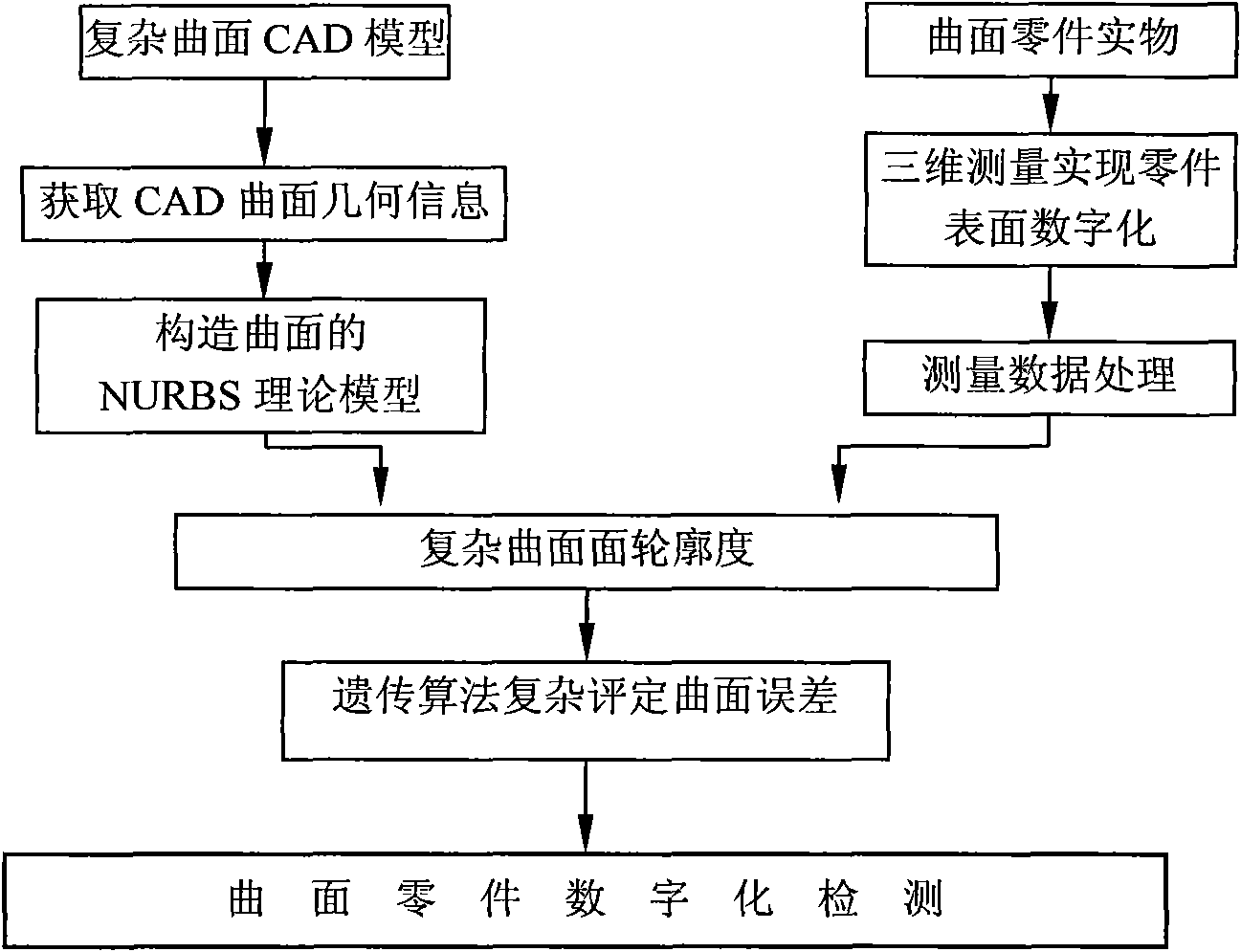
[0033] A digital detection method for complex curved surfaces, the process of which is as follows figure 1 As shown, the method includes the following steps:

[0034] (1) Extract the geometric data of the CAD model of the complex surface, establish the NURBS theoretical model of the complex surface, and then use the three-dimensional measurement of the actual surface part to digitize the surface of the part to obtain the measurement point parameters;

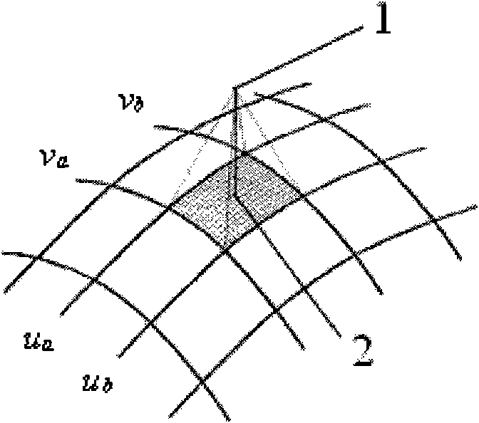
[0035] (2) Construct the isoparametric line area by searching two sets of isoparametric line closest to the measuring point on the CAD surface, and establish the binary nonlinear mathematical model of the minimum distance from the measuring point to the surface isoparametric line area;

[0036] (3) The genetic algorithm is used to calculate the shape error of the complex surface, and the error evaluation of the complex surface is realized.

[0037] Using the NURBS method to describe the theoretical model of the CAD surface, the...


PUM


Abstract

The invention relates to a digitizing detection method of a complicated curved face. The method comprises the following steps: (1) extracting the geometric data of a CAD model of the complicated curved face, establishing an NURBS theoretical model of the complicated curved face, measuring a part object with the curved face by a three-coordinate measuring machine, digitizing the surface of the partto obtain the parameter of a measuring point; (2) establishing a binary nonlinear mathematical model with the minimum distance from the measuring point to an isoparametric line areas of the curved face by searching two groups of isoparametric line areas with isoparametric line structure proximate to the measuring point on the CAD curved face; and (3) calculating the shape error of the complicatedcurved face by a genetic algorithm to realize the error estimation of the complicated curved face. Compared with the prior art, the invention establishes an accurate curved face theoretical model, enhances the searching efficiency, can ensure the acquisition of a globally optimal solution and lightens the measuring intensity.

Description

technical field [0001] The invention relates to the technical field of mechanical design and detection, in particular to a digital detection method for complex curved surfaces. Background technique [0002] With the rapid development of modern manufacturing industry and the increasing maturity of surface design and processing technology in CAD / CAM, high-tech, high-performance mechanical equipment such as propellers, screw pumps, compressors, extruders, steam turbines, blowers and other complex surfaces The demand for parts is increasing, and they are widely used in many important industrial fields of the national economy, such as military, aviation, energy, machinery, chemical industry, and new materials, and their manufacturing accuracy directly affects the working performance and quality of equipment . [0003] The digital detection of shape error of complex curved surface refers to the use of advanced measuring equipment to measure complex curved surface parts, obtain di...

Claims


Application Information

Patent Timeline
Patent Type & Authority Applications(China)
IPC IPC(8): G01B21/20
Inventor 郭慧林大钧潘家祯
Owner EAST CHINA UNIV OF SCI & TECH
Learn More