Reference current generating circuit applied to low operating voltage

A technology of reference current and circuit generation, which is applied in the direction of adjusting electrical variables, control/regulation systems, instruments, etc., can solve the problem of insufficient operating range, etc., and achieve the effects of reducing chip area and cost, improving phase margin, and loop stability

Active Publication Date: 2010-03-24
FARADAY TECH CORP
View PDF0 Cites 11 Cited by
  • Summary
  • Abstract
  • Description
  • Claims
  • Application Information

AI Technical Summary

Problems solved by technology

figure 2 The reference current generation circuit of the reference current generation circuit lacks a layer of NMOS transistors, so there is no problem of insufficient operating range, but because the circuit adds two more stages of gain, and its output point is high impedance, if you want to use a capacitor to ground for phase compensation, requires a relatively large chip area to achieve good stability

Method used


Image

  • Reference current generating circuit applied to low operating voltage
  • Reference current generating circuit applied to low operating voltage
  • Reference current generating circuit applied to low operating voltage

Examples


Embodiment Construction

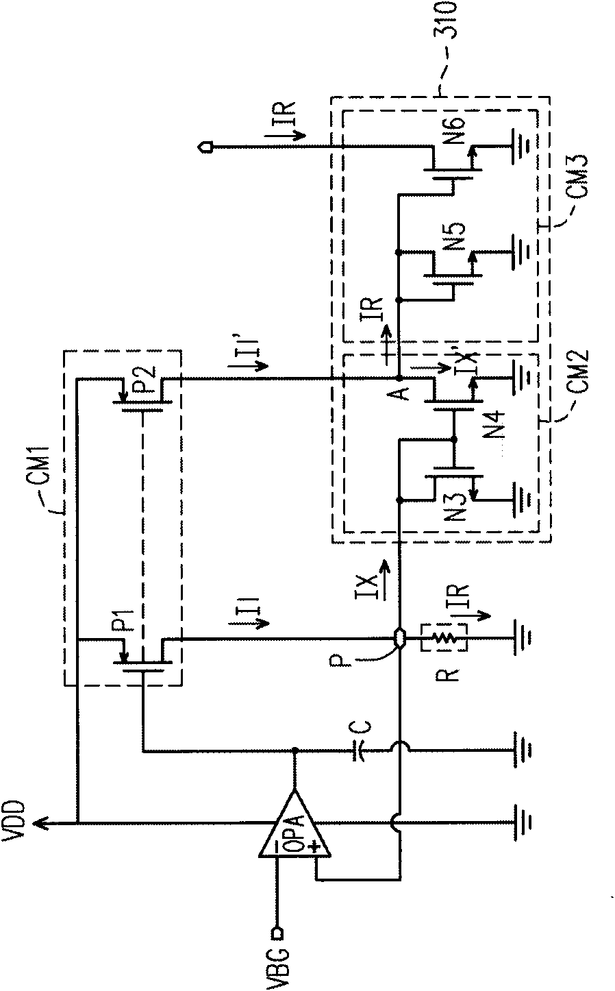
[0027] image 3 It is a schematic diagram of a reference current generating circuit capable of operating at low voltage according to an embodiment of the present invention. For the following description, please refer to image 3 . image 3 The reference current generating circuit includes an operational amplifier OPA, a capacitor C, an external resistor R, a current mirror CM1, and a compensation circuit 310, wherein the compensation circuit 310 includes current mirrors CM2 and CM3. image 3 Most of the reference current generating circuit of the present invention is located in a chip, wherein the external resistor R and its grounding terminal are located outside the chip, and other parts are located in the chip. Pad P is the circuit connection point inside and outside the chip.

[0028] The negative input terminal of the operational amplifier OPA receives the reference voltage VBG from a differential reference circuit (not shown), and the positive input terminal of the oper...


PUM


Abstract

A reference current generating circuit applied to low operating voltage is arranged in a chip and utilizes precise reference voltage and precise external resistance to generate precise reference current. The reference current generating circuit utilizes an equivalent resistance to be connected with the external resistance in parallel, so as to provide resistance compensation and reduce the resistance from chip pad to the interior of the chip. Moderate capacitance compensation is added, phase margin of the reference current generating circuit can be improved, and the aim of stable loop is achieved, thus reducing chip area and cost in application of low operating voltage. In addition, the reference current generating circuit utilizes a current mirror to copy the reference current generated by the external resistance, so at to solve the problem that current is influenced by parallel connection of the equivalent resistance and the external resistance.

Description

technical field [0001] The present invention relates to a reference current generating circuit capable of operating at low voltage, and more particularly to a reference current generating circuit using resistance compensation to improve phase margin. Background technique [0002] figure 1 In the prior art, an N-channel metal-oxide-semiconductor field effect transistor (NMOS transistor for short) is used as a reference current generating circuit for the second stage of an operational amplifier. figure 1 Except for the external resistor R and the ground terminal connected to the external resistor R, the circuits are all located in the same chip. A positive input terminal of the operational amplifier OPA receives a precise reference voltage VBG from a bandgapreference circuit, and a negative input terminal thereof is coupled to a pad P of the chip. Due to the virtual short circuit effect of the operational amplifier OPA, the potential of the pad P is the same as the reference...

Claims


Application Information

Patent Timeline
Patent Type & Authority Applications(China)
IPC IPC(8): G05F1/56G05F3/26
Inventor 黄鼎钧陈冠宇张原熏
Owner FARADAY TECH CORP
Why Eureka
Try Eureka