Sensor system and sampling cell assembly for use with sensor system

A sampling unit and sensor technology, applied in the direction of sensors, applications, instruments, etc., can solve the problems of short response time, low sample volume, etc., and achieve the effect of precise operation

Inactive Publication Date: 2010-03-24
RADIOMETER BASEL
View PDF3 Cites 9 Cited by
  • Summary
  • Abstract
  • Description
  • Claims
  • Application Information

AI Technical Summary

Problems solved by technology

[0012] However, although sensor systems for small-volume gas detection, such as permeate gases, have been proposed so far, there is still a need for sensor systems that combine high sensitivity, low sample volume, and short response time

Method used


Image

  • Sensor system and sampling cell assembly for use with sensor system
  • Sensor system and sampling cell assembly for use with sensor system
  • Sensor system and sampling cell assembly for use with sensor system

Examples


Embodiment Construction

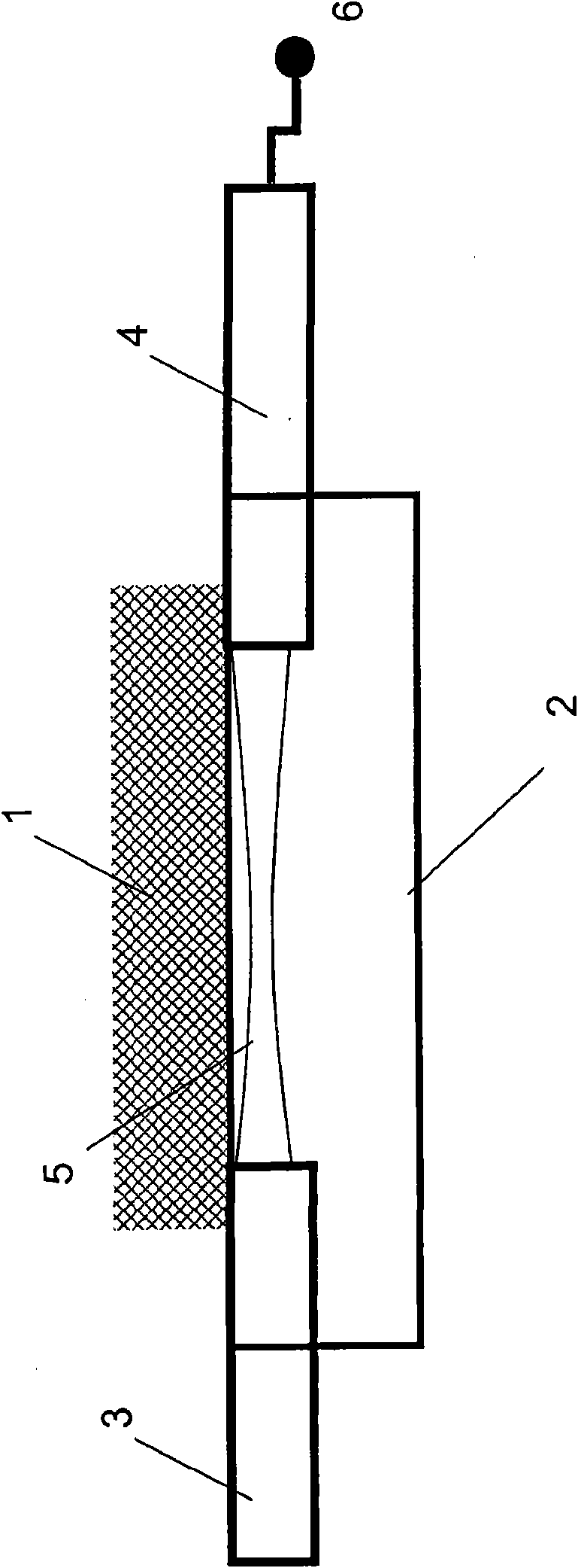
[0134] A sensor system according to the invention such as figure 1 shown. The sensor system is suitable for detecting chemical substances in a medium (1) and comprises a sampling unit (2), a light emitter (3) and a light receiver (4) arranged to generate and detect a light beam (5).

[0135] A light emitter is any device based on a light source, such as a laser, laser diode, and light emitting diode, that produces a light beam that couples light into a sampling cell. Likewise, the light receiver may be any device such as a photoelectric circuit that detects light from the sampling unit to generate an output signal (6) reflecting the concentration of the sensed chemical species in the medium.

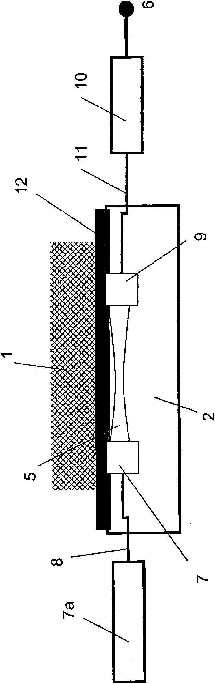
[0136] figure 2 The sensor system shown shows that the light source (7) of the light emitter can be held by the sampling unit (2) and controlled by a transmitter (8), for example by a laser controller (7a) according to current, power and / or wavelength, thereby Handles the intensity o...


PUM

PropertyMeasurementUnit
lengthaaaaaaaaaa

Abstract

A sensor system for detection of a gaseous chemical substance is provided, which comprises an optical sampling cell holding a sampling chamber of a volume of at most 20mm 3, a light emitter and a light receiver. The sampling cell is adapted for free-space propagation of the light beam. With the sensor system, high sensitivity is obtained by elimination of interferometric noise.

Description

technical field [0001] The present invention relates to sensor systems and sampling cell assemblies for use with sensor systems. Background technique [0002] In various fields of chemistry, biology and physiology, sensors for measuring parameters of test fluids are widely used. [0003] One of these areas is blood gas monitoring. Measurement of arterial blood gas parameters is an essential part of monitoring critically ill patients. Although analyzing arterial blood samples is considered the most accurate method of determining the gas status of a patient's blood, the information provided by such precise measurements only reflects the situation at the time of sample collection. Since blood gas values ​​can change rapidly under certain clinical conditions, especially in patients with unstable respiratory or cardiopulmonary status, frequent or even continuous monitoring of blood gas parameters is required to provide optimal patient care. [0004] The need for this type of m...

Claims


Application Information

Patent Timeline
Patent Type & Authority Applications(China)
IPC IPC(8): A61B5/00G01N21/03G01N21/35G01N33/49
CPCG01N2021/0346G01N21/03G01N21/7703G01N21/031G01N2021/052G01N33/4925G01N2021/399G01N21/0303A61B5/14552
Inventor 克里斯琴·迪珀辛格丹尼尔·萨尔兹曼
Owner RADIOMETER BASEL
Why Eureka
Try Eureka