
Apparatus and method for manufacturing iron block using iron pieces

A technology of iron filings and iron lumps, which is applied in the direction of improving process efficiency, etc., can solve the problems of reducing the ratio of iron filings reuse, and achieve the effects of avoiding strength reduction, minimizing weight loss, and increasing strength

Inactive Publication Date: 2010-03-24
IM STEEL
View PDF0 Cites 6 Cited by
  • Summary
  • Abstract
  • Description
  • Claims
  • Application Information

AI Technical Summary

Problems solved by technology

In this case, there will be such a problem that the reuse rate of iron filings is reduced because the amount of iron filings decreases in proportion to the increase in the amount of binder used

Method used


Image

  • Apparatus and method for manufacturing iron block using iron pieces
  • Apparatus and method for manufacturing iron block using iron pieces

Examples


Embodiment Construction

[0034] A better understanding of the technical construction and effects of the device and method for manufacturing iron blocks using iron filings according to the present invention can be obtained through the following detailed description in conjunction with the accompanying drawings, which illustrate the preferred embodiment.

[0035] Apparatus for making iron blocks

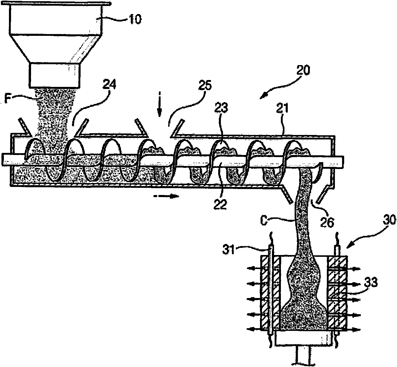
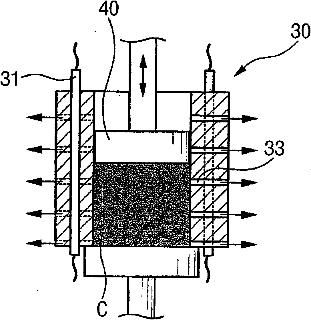
[0036] In the attached picture, figure 1 To show a schematic diagram of an apparatus for manufacturing iron blocks according to the present invention, figure 2 is a sectional view showing the shaper integrated in the device according to the present invention.

[0037] As shown in the figure, the device for manufacturing iron ingots according to the present invention includes: a stocker 10, an agitator 20 and a shaper 30, the agitator 20 is located directly below the stocker 10 and has a central shaft 22 On and around the impeller 23, the shaper 30 is located just below the end of the agitator 20 and into...


PUM


Abstract

Disclosed herein is an apparatus and a method for manufacturing an iron block from iron pieces generated during a machining process. The apparatus includes: a hopper through which chip-shaped iron pieces are introduced; an agitator positioned below the hopper, which includes one or more inlets in an upper region thereof and an outlet in a lower region thereof, and which includes an impeller internally mounted on a center shaft and rotated therearound so as to agitate the iron pieces, silicate of soda and water introduced through the inlets; and a forming unit positioned below the outlet of theagitator and including a heating wire embedded in an inner wall thereof. The invention has advantages of minimized weight loss and increased hardness, and the moisture content contained in the iron block is minimized, thus avoiding a decrease in hardness attributable to corrosion during the storage and the transportation.

Description

technical field [0001] The present invention relates to an apparatus and method for manufacturing iron ingots from iron filings generated during machining, and more particularly, to an apparatus and method for manufacturing iron ingots from iron filings, said method being suitable for use in Sodium silicate and water mix iron filings produced during the machining of mechanical parts, agitate the mixture, and compress the mixture into forming cavities while heating it, resulting in an iron block with minimal weight loss and enhanced hardness. Background technique [0002] Generally, when various metal parts including mechanical parts are machined using a general-purpose machine tool, lathe, or milling machine, cutting of the parts constantly generates curled iron filings. [0003] In addition, in steel mills and manufacturing sites, slag powder, which is an unnecessary lump generated in the manufacture of metal products, spreads and accumulates around the manufacturing site. ...

Claims


Application Information

Patent Timeline
Patent Type & Authority Applications(China)
IPC IPC(8): C22B1/16
CPCC22B1/005C22B1/248C22B1/243Y02P10/20C22B1/16
Inventor 扁基烈
Owner IM STEEL
Learn More