Array stimulator

一种阵列、控制器的技术,应用在电子装置领域,能够解决刺激器装置复杂性、损害植入式装置电池寿命、效率差等问题

Active Publication Date: 2010-03-31
艾弗·斯蒂芬·吉尔贝
View PDF11 Cites 31 Cited by
  • Summary
  • Abstract
  • Description
  • Claims
  • Application Information

AI Technical Summary

Problems solved by technology

The downside is the complexity of the stimulator device with 16 current-controlled outputs, and poor efficiency at moderate current outputs (which is typical of linear electronic designs), compromising the battery life of the implanted device

Method used


Image

  • Array stimulator
  • Array stimulator
  • Array stimulator

Examples


Embodiment Construction

[0114] The invention is illustrated by considering its application to transcutaneous and implantable stimulators. A drawing illustrating an electrode array may be considered to represent either a clinical situation, or a corresponding mathematical model of the tissue used to derive the appropriate component waveforms. The pulses in the figures can be considered to represent current, voltage, charge or energy, depending on the method of control used by the stimulator device.

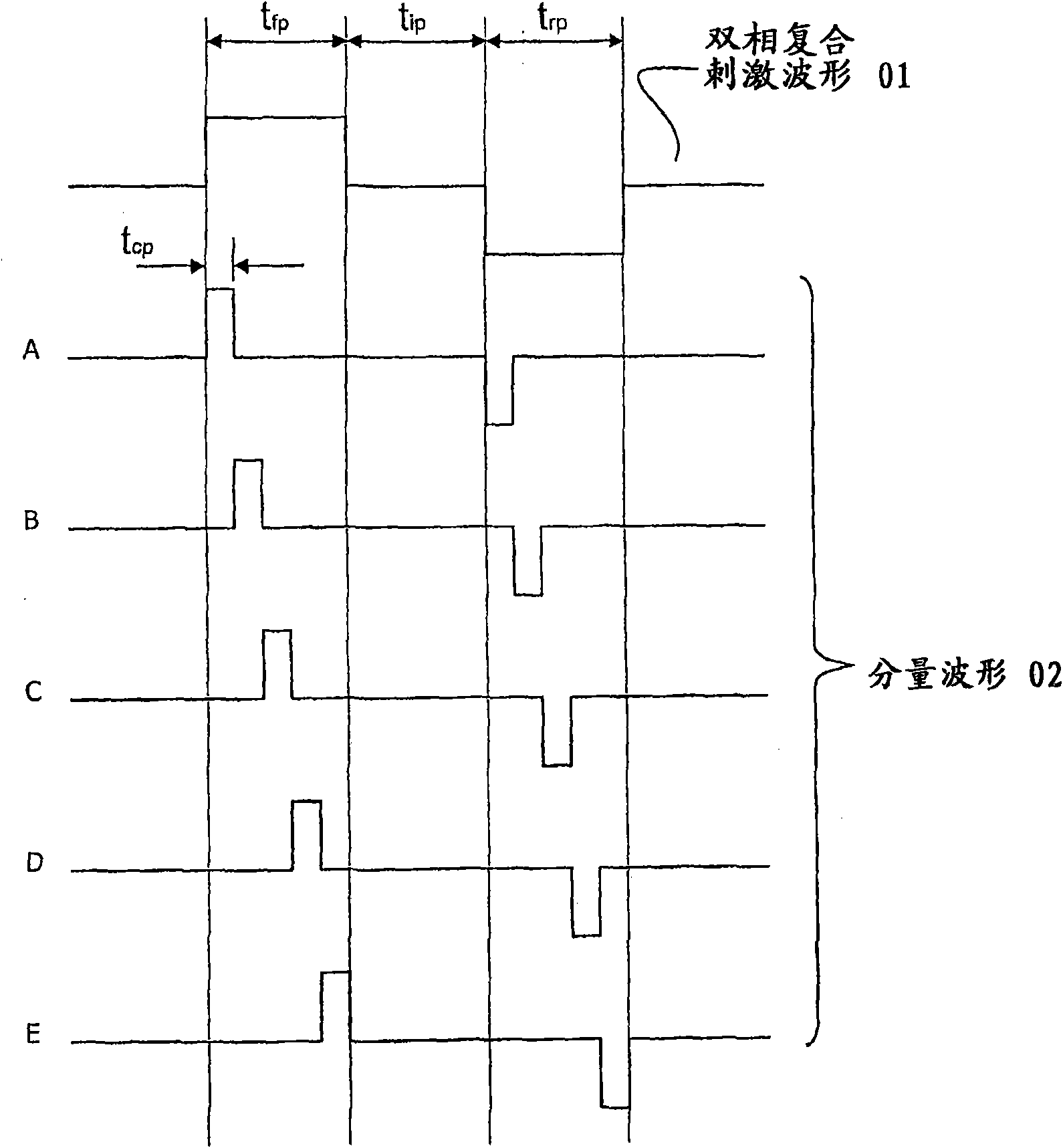
[0115] see figure 1 , waveform 01 is the complex waveform required to influence the behavior of excitable tissue, eg in transcutaneous electrical nerve stimulation applications. The waveform in this example consists of balanced forward and reverse composite pulses, the duration of the forward pulse is t fp (typically 50, 100, 500 or 1000μs), the duration of the reverse pulse is t rp , t fp = t rp , so that the net current flowing in the tissue is zero. A net current of zero is desirable because it m...


PUM


Abstract

An array stimulator has a plurality of electrodes in an array (22), the electrodes forming a plurality of electrode pairs, and a signal generator (18) for generating signals to the electrodes so as to generate electrical pulse in a patient to which the stimulator has been applied either transcutaneously or by implantation. Those electrical pulses form a composite pulse in the patient which stimulates the nervous system of the patient. The composite pulse has a duration between 4[mu]s and 1500[mu]s and a maximum voltage between 2V and 50V when the stimulator is implanted, and 15V to 500V when applied transcutaneously. The electrical pulses themselves are significantly shorter duration than the composite pulse, so they stimulate the nervous system of the patient much less than the composite pulse or not at all.

Description

technical field [0001] The present invention relates to electronic devices for generating electrical currents that affect the behavior of nerves and other excitable tissues at different distances from electrodes, and provides devices and methods for applying such devices. Background technique [0002] Electrical stimulation of nerves has been used therapeutically for more than 40 years. [0003] For example, Melzack and Wall in 1965 showed how when Aβ nerve fibers were stimulated at 100 Hz (a frequency that no other afferent nerve fibers could faithfully follow), analgesia could be produced. Wall in 1986 produced these effects by applying an electric current through a needle inserted into a patient's nerve. In order to avoid the possible negative effects of inserting needles, he soon adopted surface electrodes, which led to the term "Transcutaneous Electrical Nerve Stimulation (TENS)". [0004] A typical TENS machine forms pulses whose width can vary from 50 μs to 250 μs b...

Claims


Application Information

Patent Timeline
Patent Type & Authority Applications(China)
IPC IPC(8): A61N1/05A61N1/34
CPCA61N1/0551A61N1/36021A61N1/36071A61N1/36014A61N1/36017A61N1/0553
Inventor 艾弗·斯蒂芬·吉尔贝
Owner 艾弗·斯蒂芬·吉尔贝
Why Eureka
Try Eureka