Method and arrangement for matching an antenna

An antenna and matching circuit technology, applied in the field of small mobile terminals, matching methods and matching devices, can solve the problems that the matching circuit is not suitable for the transmitter, the output impedance of the power amplifier is low, the capacitor diode is not pressed, etc., and the adjustment algorithm is fast, Effects of reduced current consumption and improved average efficiency

Inactive Publication Date: 2010-03-31
PULSE FINLAND
View PDF4 Cites 14 Cited by
  • Summary
  • Abstract
  • Description
  • Claims
  • Application Information

AI Technical Summary

Problems solved by technology

[0008] The use of capacitive diodes in the previously described solution leads to the disadvantage that the matching circuit according to this solution is not very suitable for the transmitter, since its capacitive diodes do not behave in an acceptable way when the power is relatively high
In addition, when the power is low, the losses they generate are significant
Also, series diodes are reflective in practice, since this type of semiconductor is designed for impedance levels of 50Ω, and the output impedance of power amplifiers is usually significantly lower
A disadvantage of the solution described above is also that it involves a relatively complex regulation algorithm

Method used


Image

  • Method and arrangement for matching an antenna
  • Method and arrangement for matching an antenna
  • Method and arrangement for matching an antenna

Examples


Embodiment Construction

[0023] Figures 1 and 2 have already been explained in conjunction with the description of the prior art.

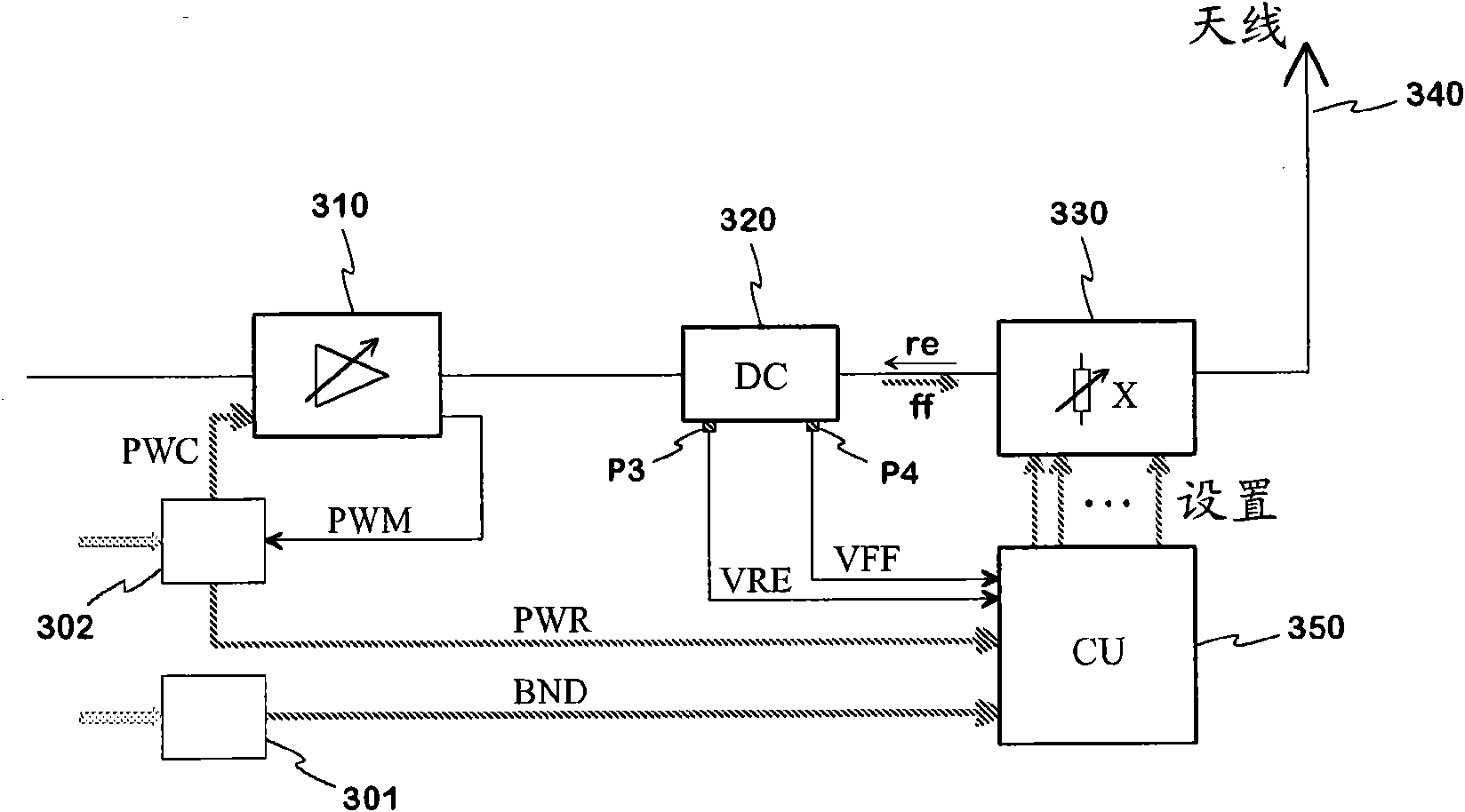
[0024] image 3 An example of an arrangement according to the invention in a transmitter of a radio device is shown in the form of a block diagram. In the transmission path of the transmitter, there are the power amplifier 310, the directional coupler 320, the reactance matching circuit 330 and the antenna 340 of the transmitter named along the direction of signal propagation. In addition to the directional coupler and the matching circuit, the control unit 350 with its coupled matching circuit belongs to the matching device.

[0025] The transmit power of the amplifier 310 can be changed by the power control signal PWC, which represents the set value of the power and is provided by the transmit power setting unit 302 . A measurement signal PWM proportional to the actual transmit power is generated in the amplifier and is used as a feedback signal to bring the transmit p...


PUM


Abstract

A method and an arrangement for matching the antenna of a radio device in transmitting condition. The antenna impedance in the output of the power amplifier of a transmitter is adjusted by means of a II-shaped reactive matching circuit, the component values of which can be selected from a relatively wide array of the alternatives. The component values are selected by means of the multiple-way switches, which only are located in the transverse branches of the matching circuit. The switches are set (706) by the control unit, input variables of which being the SWR value provided by the directional coupler, the operating band used each time and a value of the transmitting power. The matching is based on an adjusting process to be executed at regular intervals, in which process the control unit tries different combinations of the switch states and finally selects (710) the combina not tion, which brings the lowest SWR value. In the beginning of the adjusting process the control unit reduces (705), on grounds of the current values of the input variables, the number of the combinations to be tried. The antenna matching maintains relatively good, although the internal output impedance ofthe amplifier and the impedance from the output towards the antenna would strive to differ from each other for external reasons, a band changing or a change in the outptut power.

Description

technical field [0001] The invention relates to the matching of an antenna of a radio device under transmission conditions, and it includes both a matching method and a matching arrangement. The invention is particularly applicable to small mobile terminals. Background technique [0002] Matching the antenna impedance of a radio device to the power amplifier of the transmitter feeding the antenna is a usual arrangement in transmission technology. The radiation power of the antenna can be made as high as possible and proportional to the power of the power amplifier through matching. The poorer the antenna match, the higher the field strength reflected from the antenna to the power amplifier and proportional to the field strength propagating to the antenna. If a certain transmit power is required despite the reduced matching, the gain of the power amplifier must be increased, which leads to increased current consumption in the output stage and possible heating problems. [...

Claims


Application Information

Patent Timeline
Patent Type & Authority Applications(China)
IPC IPC(8): H04B1/04H03H11/30H03H7/40
CPCH04B1/0458H03H7/38
Inventor Z·米洛萨夫莱维克K·科斯基尼米P·阿纳马P·拉马钱德兰
Owner PULSE FINLAND
Why Eureka
Try Eureka