Sliding formwork control method used in motion control of virtual axis machine tool cutter

A virtual axis machine tool and motion control technology, applied in the field of virtual axis machine tools, can solve problems affecting the accuracy of the sliding mode control method, achieve the effects of reducing debugging workload, solving tremor problems, and excellent control quality

Inactive Publication Date: 2010-04-07
JIANGSU UNIV
View PDF0 Cites 20 Cited by
  • Summary
  • Abstract
  • Description
  • Claims
  • Application Information

AI Technical Summary

Problems solved by technology

[0007] When the conventional sliding mode control method is implemented by a numerical control system such as a computer, the sampling interval will cause small tremors in the control output, which will affect the accuracy of the sliding mode control method

Method used


Image

  • Sliding formwork control method used in motion control of virtual axis machine tool cutter
  • Sliding formwork control method used in motion control of virtual axis machine tool cutter
  • Sliding formwork control method used in motion control of virtual axis machine tool cutter

Examples


Embodiment

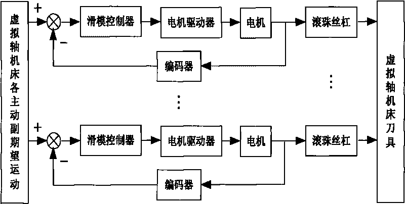
[0059] Assuming that the virtual axis machine tool is composed of 6 branch parallel mechanisms, driven by AC servo motors, and adopts rolling screw transmission (ball screw), the block diagram of its control system is as follows figure 1 shown. The specific implementation of this control method is as follows:

[0060] 1. Determine the expected movement of each active pair of the virtual axis machine tool according to the processing requirements in advance

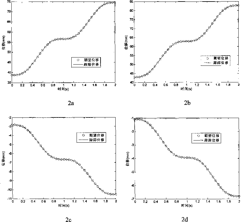
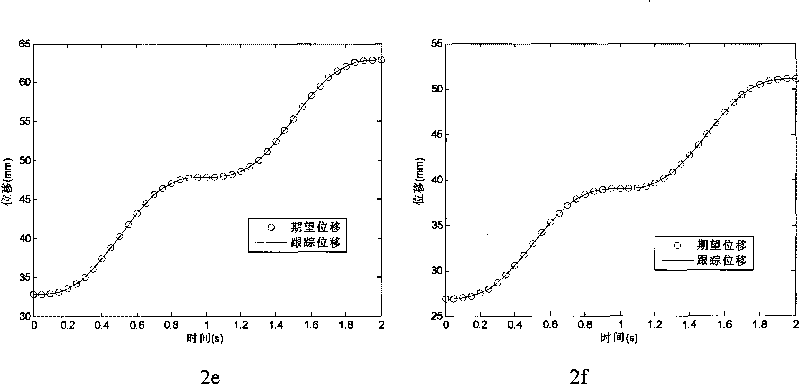
[0061] Assume that according to the processing requirements, the tool needs to move linearly from the (20mm, 20mm, 20mm) space point to the (30mm, 30mm, 30mm) space point. According to the inverse solution of the kinematics of the virtual axis machine tool, the expected motion trajectories of the active pairs of each branch of the virtual axis machine tool are obtained as follows: figure 2 The traces of the small circles in each subfigure are shown.

[0062] 2. Pre-establish the transfer function of each branch control ...


PUM


Abstract

The invention discloses a sliding formwork control method used in motion control of a virtual axis machine tool cutter, comprising the following steps: planning the space motion trail of the cutter in the processing procedure of a virtual axis machine tool; determining the expected motion trail of each active pair of the virtual axis machine tool in the processing procedure; then establishing the mathematical models of the controlled objects of each control branch circuit of the virtual axis machine tool; detecting and determining the actual motion state of each active pair of the virtual axis machine tool; calculating the function of the switching surface according to the sliding formwork control theory; determining the motor drive controlled variable of each control branch circuit of the virtual axis machine tool and sending to each motor driver; and finally driving each active pair by the motor drive controlled variable of each control branch circuit so as to drive the virtual axis machine tool cutter to realize the expected motion. In the invention, the precise models of the controlled objects of each branch circuit are not needed to be established, and the high-precision control towards the motion of the cutter can be realized by utilizing the excellent characteristics of the sliding formwork control technology; and the controlled variable of the sliding formwork is constituted by continuous functions with no trembling problems.

Description

technical field [0001] The invention relates to a virtual axis machine tool, in particular to a motion control method of a tool driven by a motor. Background technique [0002] The key technology of the numerical control system of the virtual axis machine tool (also known as parallel machine tool) is to realize the linkage control of the virtual axis through the control of the real axis of the virtual axis machine tool, so as to obtain the required tool movement trajectory. However, since the virtual axis machine tool is composed of a multi-bar parallel kinematic mechanism, its dynamic model is a complex system with multiple degrees of freedom, multiple variables, high nonlinearity, and multi-parameter coupling. During the movement of the mechanism and the machining process of the machine tool, the parameters of the mechanism model and external disturbances vary greatly, which is uncertain. Compared with ordinary machine tools with a series structure, the accumulation of tr...

Claims


Application Information

Patent Timeline
Patent Type & Authority Applications(China)
IPC IPC(8): B23Q15/00G05B19/18
Inventor 高国琴刘辛军王长勇杨年法牛雪梅
Owner JIANGSU UNIV
Why Eureka
Try Eureka