
W-shaped flame boiler disposing aperture type over-fire air spouts on stove arch

A slot-type, burn-out air technology, which is applied in the direction of combustion air/fuel supply, non-flammable liquid/gas transportation, combustion method, etc., can solve the problems of reduced boiler efficiency and low pulverized coal burnout degree.

Active Publication Date: 2010-04-14
HARBIN INST OF TECH
View PDF3 Cites 23 Cited by
  • Summary
  • Abstract
  • Description
  • Claims
  • Application Information

AI Technical Summary

Problems solved by technology

[0004] The purpose of the invention is to solve the existing W-type flame boiler in increasing the overfire air and reducing NO x At the same time, it causes the problems of low pulverized coal burnout and boiler efficiency, and then provides a W-shaped flame boiler with a slot-type burnout air device arranged on the furnace arch

Method used


Image

  • W-shaped flame boiler disposing aperture type over-fire air spouts on stove arch
  • W-shaped flame boiler disposing aperture type over-fire air spouts on stove arch
  • W-shaped flame boiler disposing aperture type over-fire air spouts on stove arch

Examples


specific Embodiment approach 1

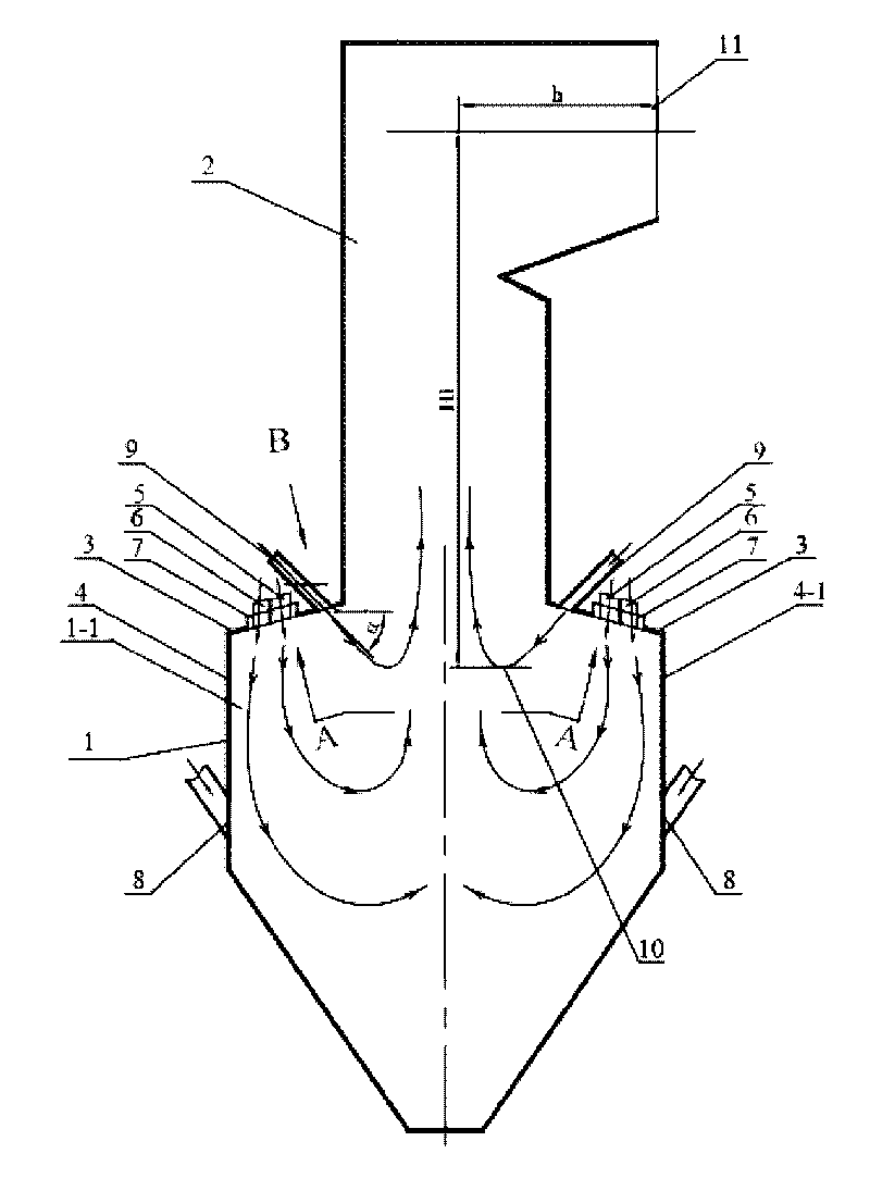
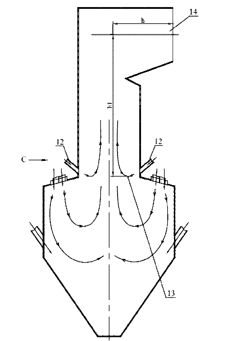
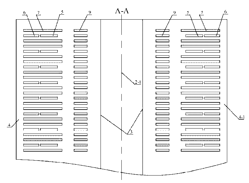
[0011] Specific implementation mode one: combine figure 1 and image 3 Describe this embodiment, the W-shaped flame boiler with slot-type overburning air nozzles arranged on the furnace arch described in this embodiment includes a furnace body composed of a lower furnace body 1, an upper furnace body 2 and two furnace arches 3 and A plurality of primary air nozzles 5, a plurality of exhaust gas nozzles 6 and a plurality of secondary air nozzles 7; the W-shaped flame boiler also includes a plurality of slit-type burn-off air nozzles 9; a plurality of secondary air nozzles 7 are divided into two groups , two groups of secondary air nozzles 7 are arranged symmetrically along the center line of the furnace body, and a group of secondary air nozzles 7 are parallelly arranged on each furnace arch 3 along its length direction, and a plurality of secondary air nozzles 7 are all connected with the lower furnace body The lower furnace of 1 is connected, and the two adjacent secondary ...

specific Embodiment approach 2

[0012] Embodiment 2: In this embodiment, the angle α between the centerline and the horizontal line of each slit-type overburning air nozzle is 25°. Other components and connections are the same as those in the first embodiment.

specific Embodiment approach 3

[0013] Specific implementation mode three: combination image 3 To describe this embodiment, the cross-section of the slit-type overburning air nozzle 9 in this embodiment is a rectangle with an aspect ratio of (5-7):1. Other compositions and connections are the same as those in Embodiment 1 or 2.


PUM


Abstract

A W-shaped flame boiler disposing aperture type over-fire air spouts on a stove arch relates to a W-shaped flame boiler. The invention aims at solving the problems of existing W-shaped flame boilers that the burnout degree of coal powder is low, and the efficiency of the boiler is reduced when simultaneously increasing over-fire air and reducing the discharge of NOx. A plurality of the aperture type over-fire air spouts are divided into two groups, the two groups of the aperture type over-fire air spouts are symmetrically arranged along the central line of a boiler body, a group of aperture type over-fire air spouts are correspondingly arranged on each stove arch near the neck aperture of a hearth, one group of the aperture type over-fire air spouts are arranged in parallel along the length direction and are all communicated with a lower hearth of the lower boiler body, the sections of the aperture type over-fire air spouts are rectangles with the ratio of length to width is (5-7):1, and the central line of each aperture type over-fire air spout and the horizontal line form an included angle of 20-35 degrees. The distance between adjacent aperture type over-fire air spouts is 100 mm. The setting of the aperture type over-fire air spouts prolongs the reacting time between uncombusted coal powder granules and the over-fire air, and enables the combustion to be more compete.

Description

technical field [0001] The invention relates to a W-shaped flame boiler, in particular to a W-shaped flame boiler with a gap-type burn-off air device arranged on a furnace arch, and belongs to the technical field of W-shaped flame boiler combustion. Background technique [0002] W-type flame boiler is a boiler specially designed for burning anthracite and lean coal. In order to meet the needs of timely ignition and stable combustion of difficult-to-burn coal, the furnace must maintain a high temperature level, resulting in NO x Emission levels were significantly higher. Domestic active W-type flame boiler NO x The emission level is mostly at 1100mg / m 3 Above, some boilers are even as high as 1800~2000mg / m 3 . According to the "Emission Standards for Air Pollution from Thermal Power Plants" (GB13223-2003) that came into effect on January 1, 2004, for the combustion of V daf For thermal power boilers with less than 10% coal type, the maximum allowable emission concentrati...

Claims


Application Information

Patent Timeline
IPC IPC(8): F23C7/00F23L9/00F23L1/00
Inventor 李争起陈智超况敏朱群益张佳申珊平孔维光
Owner HARBIN INST OF TECH
Learn More