
Sub-threshold reference source compensated by adopting electric resistance temperature

A technology of resistance temperature and reference source, which is applied in the direction of adjusting electrical variables, control/regulation systems, instruments, etc., can solve problems such as poor compatibility of BJT tubes, lower reference voltage, amplifier imbalance, etc., and achieve stable power supply voltage and low power consumption. consumption, the effect of simple structure

Inactive Publication Date: 2010-04-21
BEIJING JIAOTONG UNIV
View PDF0 Cites 17 Cited by
  • Summary
  • Abstract
  • Description
  • Claims
  • Application Information

AI Technical Summary

Problems solved by technology

However, because there are many problems in the realization of the bandgap reference source in the CMOS process, its development is limited by many factors, and there are the following problems: due to the poor compatibility of the BJT tube in the CMOS process, the amplifier’s offset problem will occur, Therefore, the bandgap reference source implemented on the CMOS process line will have the problem of whether the BJT tube can be accurately realized and how to reduce the amplifier offset
The more commonly used reference voltage sources are mainly based on V th self-biased structure, but this reference voltage source has the disadvantage of poor temperature coefficient
[0004] In addition, with the continuous reduction of power supply voltage, the reference voltage required in the circuit is also continuously reduced, and it is difficult for a general bandgap reference voltage source to generate a reference voltage lower than 0.6V at room temperature

Method used


Image

  • Sub-threshold reference source compensated by adopting electric resistance temperature
  • Sub-threshold reference source compensated by adopting electric resistance temperature
  • Sub-threshold reference source compensated by adopting electric resistance temperature

Examples


Embodiment Construction

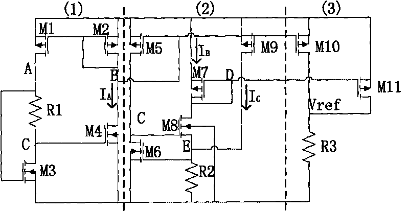
[0016] The invention provides a subthreshold reference source using resistance temperature compensation. The reference source is realized by CMOS technology, has a simple structure, and has good temperature stability, stable power supply voltage, power consumption, PSRR and other characteristics.

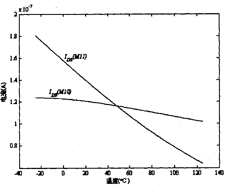
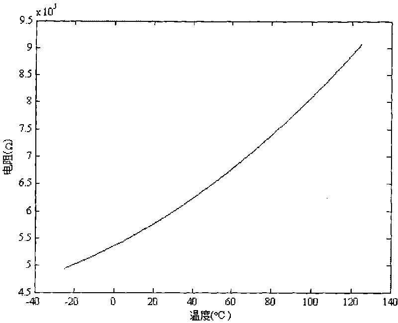
[0017] The schematic diagram of the subthreshold reference source using resistance temperature compensation is as follows figure 1 As shown, it includes: a peak current mirror circuit 1, a negative temperature coefficient current generation circuit 2 and a reference voltage output circuit 3. The working principle of the reference source is to generate two negative temperature coefficient currents I through the peak current mirror circuit and the negative temperature coefficient current generating circuit. A and I B (Such as figure 2 shown), and superimpose the two negative temperature coefficient currents, and flow through the resistor R3 with a positive temperature coefficient (...


PUM


Abstract

The invention discloses a sub-threshold reference source compensated by adopting electric resistance temperature, which belongs to a range of power supply temperature compensating circuits. The sub-threshold reference source adopts positive temperature coefficient compensating circuit and temperature compensating reference voltage source technology of electric resistance, and consists of three parts comprising a peak current mirror, a negative temperature coefficient current generating circuit and a reference voltage output circuit. A sub-threshold reference circuit for generating constant reference voltage output by using the positive temperature coefficient of the electric resistance and the negative temperature coefficient of the current on a resistor can overcome the influence that the output voltage brought by channel length modulation effect is changed by the fluctuation of power supply voltage to a certain degree; and the sub-threshold reference source has a simple structure and low power consumption, can be applied to an analog integrated circuit with low-power consumption design, and can be broadly applied to a reference voltage source circuit required by a low-power consumption analog and digital-analog mixed circuit for generating low temperature coefficients.

Description

technical field [0001] The invention belongs to the scope of power supply temperature compensation circuits, in particular to a sub-threshold reference source using resistance temperature compensation widely used in low power consumption design, especially to a positive temperature coefficient compensation circuit and temperature compensation reference using resistance resistance The voltage source is mainly used in low-power analog and digital-analog hybrid circuits that need to generate low temperature coefficient reference voltage source circuits. Background technique [0002] The function of the reference voltage source is to provide a reference voltage to other functional modules in the circuit. As the most basic circuit module, it is widely used in analog and mixed circuits such as operational amplifiers, ADCs, and DACs. The stability of the reference voltage source directly determines the quality of the circuit performance. The indicators to measure the stability of ...

Claims


Application Information

Patent Timeline
IPC IPC(8): G05F3/30
Inventor 骆莉蔡晓伟
Owner BEIJING JIAOTONG UNIV
Learn More