Inspection robot wheel-claw compound mechanism

An inspection robot and wheel claw technology, applied in the field of robotics, can solve the problems of difficulty in robot offline, poor safety protection, complex walking structure, etc., and achieve the effects of light weight, high clamping efficiency and compact system structure

Inactive Publication Date: 2010-04-28
昆山市工业技术研究院有限责任公司
View PDF0 Cites 46 Cited by
  • Summary
  • Abstract
  • Description
  • Claims
  • Application Information

AI Technical Summary

Problems solved by technology

[0003] In order to solve the shortcomings of the existing high-voltage line inspection robot, such as complex walking structure, heavy weight, high energy consumption, poor safety protection when walking, and difficulty in getting the

Method used


Image

  • Inspection robot wheel-claw compound mechanism
  • Inspection robot wheel-claw compound mechanism
  • Inspection robot wheel-claw compound mechanism

Examples


Embodiment Construction

[0023] The technical solution of the present invention will be described in further detail below through the embodiments and accompanying drawings.

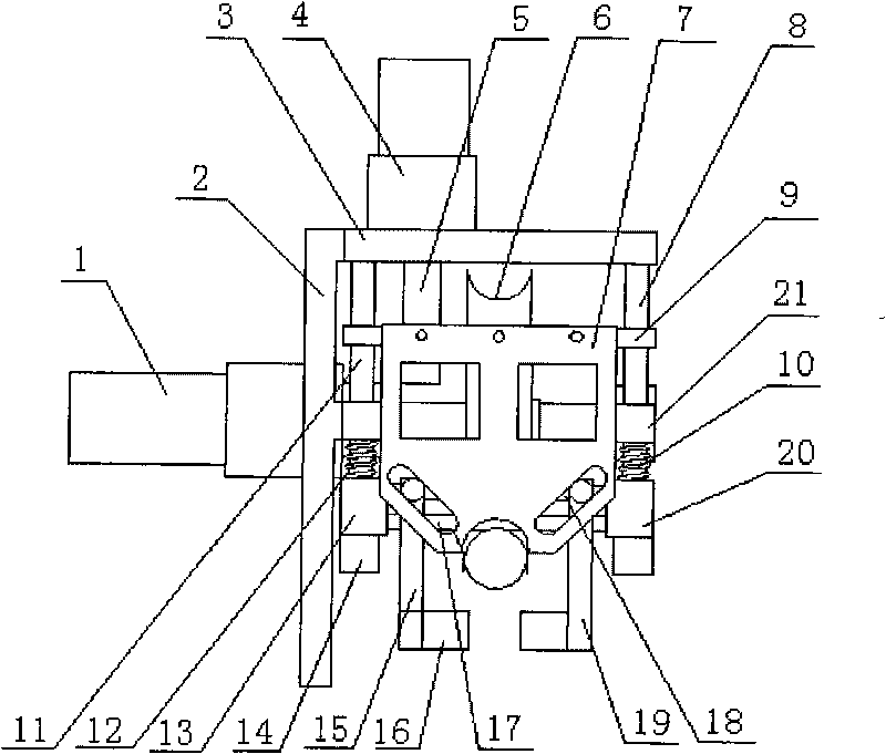
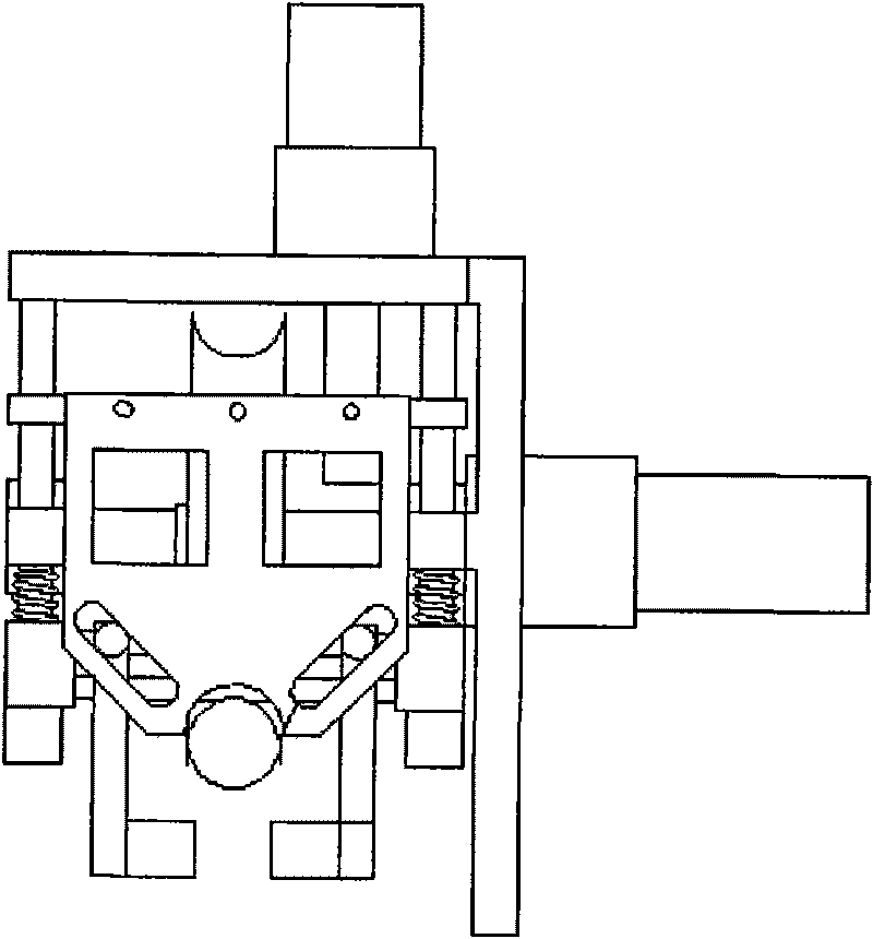
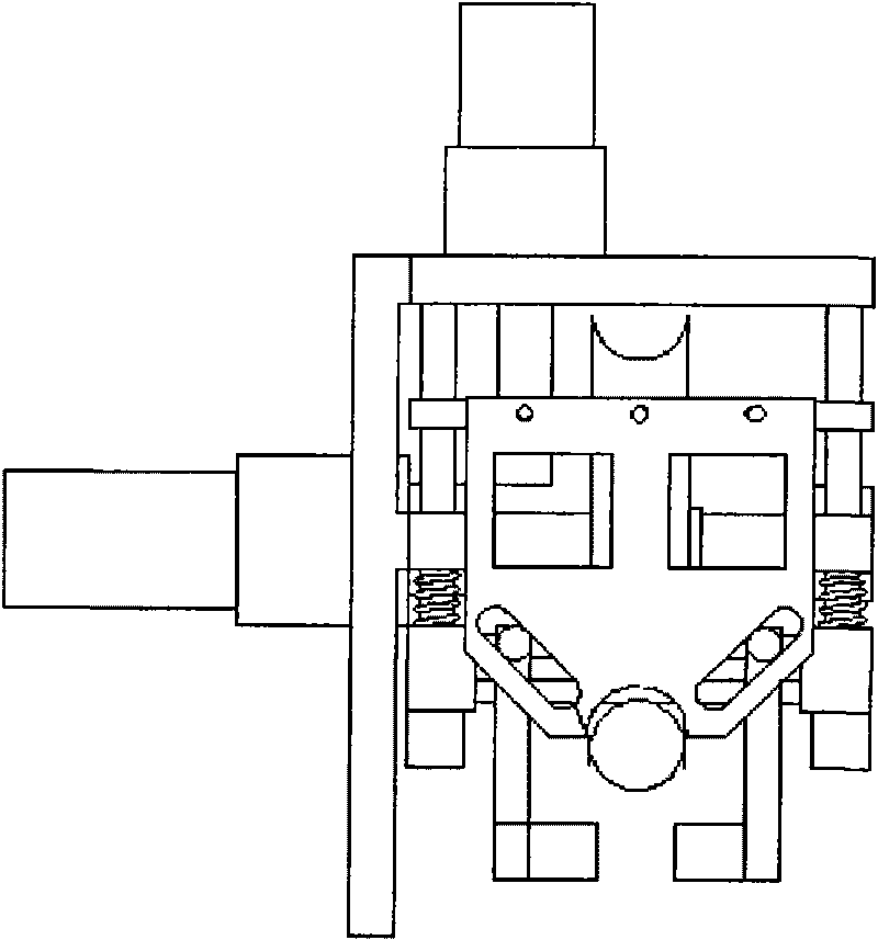
[0024] figure 1 It is a structural schematic diagram of the wheel claw compound mechanism of the inspection robot of the present invention; figure 2 is the back view of the figure; image 3 It is a schematic diagram of the released state of the embodiment of the present invention; Figure 4 It is a schematic diagram of the closed state of the embodiment of the present invention; Figure 5 It is a schematic diagram of the clamping state of the embodiment of the present invention; Figure 6 It is the left view of the wheel and claw compound mechanism of the inspection robot of the present invention.

[0025] The illustration is introduced with the structure of four vertical polished rods and two horizontally moving lead screws at the front and rear respectively, but the present invention is not limited thereto, and equivalent ...


PUM

PropertyMeasurementUnit
Slopeaaaaaaaaaa

Abstract

The invention relates to an inspection robot wheel-claw compound mechanism, comprising a walking drive mechanism and a front clamping mechanism and a rear clamping mechanism. A clamping motor is mounted on the top plate of an arm; the output shaft is matched with a screw with thread on a lifting plate through a screw rod; the lifting plate is sheathed on a vertical polish rod which is mounted at the lower side of the top plate; a front sliding plate and a rear sliding plate are respectively mounted in the front and the rear of the lifting plate; two sides of the lower side of the sliding plate are respectively provided with a guide groove, the bottom of which closes up to the middle; a left clamping jaw and a right clamping jaw are movably mounted on a horizontal moving screw rod, the two ends of which are connected with the vertical polish rod; sliding blocks on the clamping jaws are inserted in the guide groove; rolling wheels are mounted on the tail ends of the clamping jaws; the rear clamping mechanism has the same structure with the front clamping mechanism. In the invention, one motor is used to drive the clamping jaws to move in two directions, thus the structure is simple and the cost is saved; and meanwhile, the positive pressure between a walking wheel and a line is increased via the clamping action of the clamping jaw, thereby increasing friction force, realizing stronger driving capacity; the inspection robot wheel-claw compound mechanism of the invention has high clamping efficiency, light weight and wide application range.

Description

technical field [0001] The invention relates to a robot structure, in particular to a robot motion mechanism for walking and clamping along an overhead cable, and belongs to the technical field of robots. Background technique [0002] The line inspection robot is a complex mechatronics system, involving many fields such as mechanical structure, automatic control, communication, sensor information fusion, and power supply technology. In the process of walking on a large slope line, the line inspection robot needs to increase the friction between the walking wheel and the line to realize the effective driving of the robot (document 1Xinglong Zhu, Hongguang Wang, Fang Lijin, Mingyang Zhao, Jiping Zhou.An Autonomous Obstacles Negotiating Inspection Robot for Extra-High Voltage PowerTransmission Lines.In: The Ninth International Conference on Control, Automation, Robotics and Vision, Singapore, 2006; Literature 2Montambault, S. and Pouliot, N., 2007, "Design and Validation of a M...

Claims


Application Information

Patent Timeline
IPC IPC(8): B25J5/00B25J15/00B25J13/00B60K7/00H02G1/02
Inventor 王鲁单程胜张建伟赵广志许少强王臻
Owner 昆山市工业技术研究院有限责任公司
Why Eureka
Try Eureka