Device for detecting thickness of photoresist on curved surface and method for detecting thickness of photoresist on curved surface point by point

A detection device and curved surface technology, applied in the direction of measuring devices, optical devices, instruments, etc., can solve the problems that the accuracy and accuracy cannot be guaranteed, and there is no thickness distribution of photoresist.

Inactive Publication Date: 2010-05-05
ZHEJIANG UNIV
View PDF0 Cites 7 Cited by
  • Summary
  • Abstract
  • Description
  • Claims
  • Application Information

AI Technical Summary

Problems solved by technology

However, in the measurement of the curved surface adhesive layer, the precision and accuracy cannot be guaranteed, and the results need to be corrected after the measureme

Method used


Image

  • Device for detecting thickness of photoresist on curved surface and method for detecting thickness of photoresist on curved surface point by point
  • Device for detecting thickness of photoresist on curved surface and method for detecting thickness of photoresist on curved surface point by point
  • Device for detecting thickness of photoresist on curved surface and method for detecting thickness of photoresist on curved surface point by point

Examples


Embodiment Construction

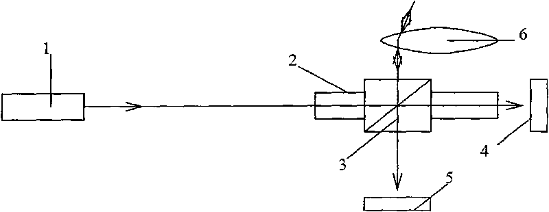
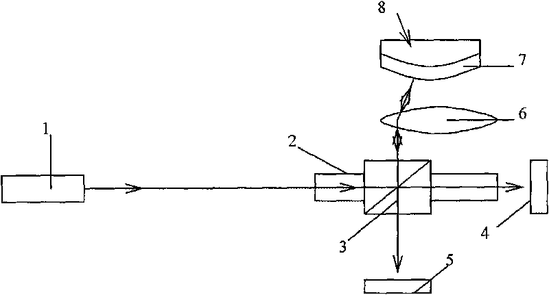
[0025] Such as figure 1 As shown, the point-by-point detection device for curved surface glue thickness of the present invention mainly includes: a laser transmitter 1 , a guide rail 2 , a beam splitting prism 3 , a first optical power meter 4 , a second optical power meter 5 and a lens 6 . Wherein, the dichroic prism 3 is arranged on the guide rail 2 . The dichroic prism 3 can move along the guide rail 2 to change the direction of the outgoing light passing through the dichroic prism 3 . The spherical center of the curved surface of the sample to be tested is located at the focal point of the lens 6, and the sample to be tested is held by a holder. The first optical power meter 4 and the second optical power meter 5 synchronously record the intensity of the transmitted light from the dichroic prism 3 and the light intensity of the reflected light reflected from the adhesive layer of the substrate.

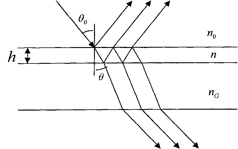
[0026] When using the detection device of the present invention to detect t...


PUM


Abstract

The invention discloses a device for detecting thickness of photoresist on a curved surface and a method for detecting thickness of photoresist on the curved surface point by point. The device comprises a laser transmitter, a guide, a beam splitter prism, a first optical power meter, a second optical power meter and a lens, wherein the beam splitter prism is arranged on the guide; the light rays transmitted by the laser transmitter irradiate the beam splitter prism; the transmitted light rays passing through the beam splitter prism irradiate the first optical power meter; the reflected light rays passing through the beam splitter prism irradiate the lens; the light rays passing through the lens enter along the direction of the center of sphere of the curved surface on a photoresist layer of a detected sample, return along an entrance light path after being reflected by the detected curved surface on the photoresist layer and irradiate the second optical power meter after passing through the lens and the beam splitter prism in turn. The invention can realize point-by-point measurement of the thickness and distribution of the photoresist on the substrate of the curved surface without destruction.

Description

technical field [0001] The invention relates to a method for non-destructive single-point measurement of photoresist thickness on a curved substrate. Background technique [0002] With the development of lithography technology, curved surface laser direct writing technology has become a new direction for the development of lithography technology. The thickness distribution of the surface adhesive layer determines the effect of the final three-dimensional relief microstructure. Theoretically, the adhesive thickness distribution of the curved surface substrate is uneven, and the unevenness is related to the curvature of the substrate, so it is necessary to obtain the accurate thickness distribution of the adhesive layer. [0003] Among the existing measurement techniques, the step meter method and the ellipsometer method are more suitable for the measurement of glue thickness. The pedometer method is a stress method, which destroys the surface of the adhesive layer, and can ...

Claims


Application Information

Patent Timeline
IPC IPC(8): G01B11/06
Inventor 张春晖梁宜勇陈龙江罗剑波
Owner ZHEJIANG UNIV
Why Eureka
Try Eureka