Bus and bus assembly for electric transmission

A technology for power transmission and busbars, applied in the field of busbars and their busbar assemblies, can solve problems such as unprovided connections, and achieve the effects of increasing the contact area between metals, good electrical conductivity, and high bonding strength

Inactive Publication Date: 2010-05-05
晏新海
View PDF1 Cites 2 Cited by
  • Summary
  • Abstract
  • Description
  • Claims
  • Application Information

AI Technical Summary

Problems solved by technology

It can be seen that this document does not provide technical inspiration for applying its aluminum-copper casting conductive joint to the connection between busbars

Method used


Image

  • Bus and bus assembly for electric transmission
  • Bus and bus assembly for electric transmission
  • Bus and bus assembly for electric transmission

Examples


Embodiment 1

[0084] (Example 1, busbar for power transmission)

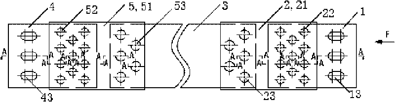
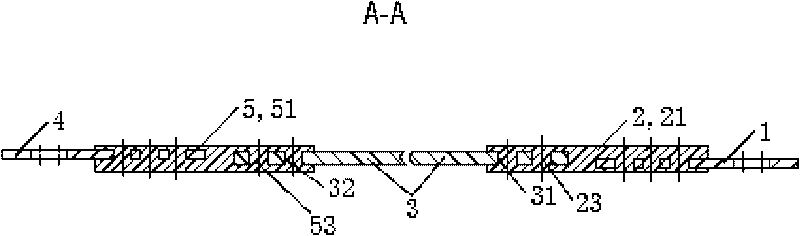
[0085] See figure 1 , The bus bar for power transmission in this embodiment includes a first copper plate 1 , a first cast aluminum plate 2 , an aluminum bar 3 , a second copper plate 4 and a second cast aluminum plate 5 .

[0086] See figure 2 The aluminum row 3 includes a group of round holes 31 perpendicular to the plate surface of the aluminum row 3 on the left end of the aluminum row 3 on the aluminum row 3 and the right end of the aluminum row 3 on the aluminum row 3 Another group of circular holes 32 perpendicular to the plate surface of the aluminum row 3.

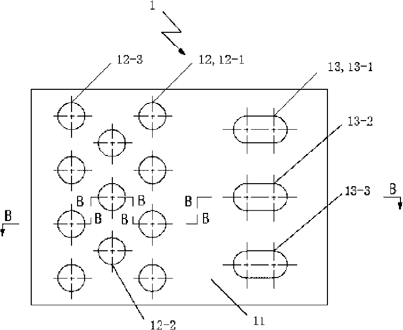
[0087] See image 3 and Figure 4 , the first copper plate 1 is a stamped pure copper rectangular plate with a thickness of 3 to 5 millimeters (4 millimeters in this embodiment), which includes the first pure copper plate body 11, the first pure copper plate body 11 located on the first pure copper plate body 11 Eleven connecting holes 12 perpendicular to th...

Embodiment 2

[0103] (Example 2, busbar for power transmission)

[0104] The rest of the busbar for power transmission in this embodiment is the same as that in Embodiment 1, except that:

[0105] See Figure 11 , a group of bolt holes 13 on the first copper plate 1 has 6 in total, divided into two rows on the left and right, and a row on the left side has 3 bolt holes 13, each of which is a waist hole, and is distributed at equal intervals according to the up and down direction, from top to bottom These are the first bolt hole 13-1, the second bolt hole 13-2 and the third bolt hole 13-3 in sequence. There are three bolt holes 13 in a row on the right side, each of which is a round hole, and is equally spaced according to the up and down direction, and from top to bottom are the fourth bolt hole 13-4, the fifth bolt hole 13-5 and the sixth bolt Holes 13-6.

[0106] See Figure 12 , a group of bolt holes 43 of the second copper plate 4 has 6 in total, divided into left and right rows, an...

Embodiment 3

[0108] (Example 3, busbar assembly for power transmission)

[0109] Select the 4 busbars obtained in Example 1, among which 3 with larger dimensions are used as A, B, and C three-phase lines, and another one with the same structure and smaller size is used as the neutral line. See Figure 15 , The busbar assembly for power transmission in this embodiment further includes an insulating frame 7 , a square pipe 8 and an insulating mounting block 6 .

[0110] See Figure 14 , The insulating frame 7 includes an upper insulating frame 71 and a lower insulating frame 72 . The overall shape of the upper insulating frame 71 and the lower insulating frame 72 is cuboid, made of insulating ceramics. The upper part of the lower insulating frame 72 is provided with 4 front and rear equally spaced grooves from left to right. The 3 grooves on the left have the same shape, and the groove on the far right is slightly smaller than the groove on the left. The bottom of the upper insulating f...


PUM


Abstract

The invention relates to a bus and a bus assembly for electric transmission. The bus for electric transmission comprises two copper plates, two aluminum casting plates and an aluminum bus bar, wherein the two copper plates are respectively positioned at the left side and the right side of the aluminum bus bar; when the aluminum casting plates are molded in a press casting way, one end of a plate body of each copper plate and one end of the aluminum bus bar are used as inserts for being coated in the aluminum casting plates; and both the exposing sides of the two copper plates are provided with bolt holes. The bus assembly for electric transmission comprises four to five buses, a square pipe, two insulating installation blocks and other fittings, wherein the four to five buses are vertically arranged along the left direction and the right direction; and rectangular holes matched with the left end and the right end of the buses are arranged in the two insulating installation blocks, respectively sleeved at both ends of the buses and inserted into the left end and the right end of the square pipe. The product has good conducting performance, high reliability and long service life and can form an electric line for transmitting low-voltage heavy current at a long distance.

Description

technical field [0001] The invention relates to a busbar for electric power supply or distribution and a busbar assembly thereof. Background technique [0002] Industrial and mining enterprises generally use self-built substations for production, office and daily use of electricity. The power supply company sends power to the substation through high voltage, and after converting it into 380V / 220V power, the power is sent to the power cabinets by connecting cables. , and then connect the electrical equipment to the electrical cabinet to obtain electricity. [0003] The traditional structure is to use cables to send power directly. With the increase and centralization of power consumption, in order to reduce line loss, facilitate power distribution and power supply line construction and maintenance, some industrial and mining enterprises have adopted the structure of copper bus power supply. The so-called busbar actually uses copper bars instead of traditional cables to dire...

Claims


Application Information

Patent Timeline
Patent Type & Authority Applications(China)
IPC IPC(8): H01R4/62H01R4/70H01B5/02H02G5/00
Inventor 晏新海晏日安
Owner 晏新海
Why Eureka
Try Eureka