
Power factor correcting controller and control method and applied power supply converter thereof

A power factor correction, power converter technology, applied in the output power conversion device, high-efficiency power electronic conversion, irreversible AC power input conversion to DC power output and other directions, can solve the adverse light load efficiency, output voltage Vout fluctuation, Unfavorable problems such as light-load efficiency of post-stage DC/DC converters

Inactive Publication Date: 2010-05-05
LITE ON TECH CHANG ZHOU CO LTD +2
View PDF0 Cites 23 Cited by
  • Summary
  • Abstract
  • Description
  • Claims
  • Application Information

AI Technical Summary

Problems solved by technology

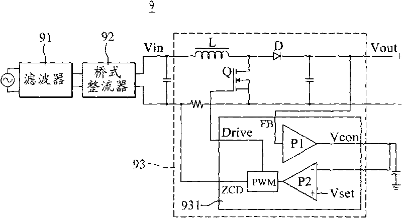
[0009] However, as the requirements for power supply light-load efficiency and no-load loss become more and more stringent, the above-mentioned frequency hopping control method has been difficult to meet the requirements of various international standards, such as: Environmental Protection Agency (EPA), Energy Star and other energy-saving related standards
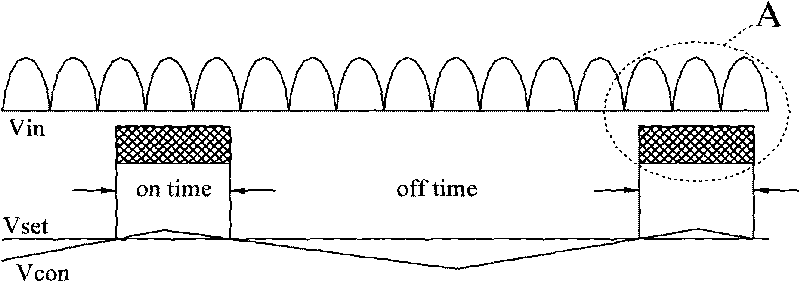
Moreover, the frequency hopping operation performed by the conventional critical conduction mode power factor correction circuit 93 when the load is light will cause large fluctuations in the output voltage Vout, which is not conducive to improving the light-load efficiency of the subsequent DC / DC converter. optimization, which is not conducive to the improvement of the overall light load efficiency

Method used


Image

  • Power factor correcting controller and control method and applied power supply converter thereof
  • Power factor correcting controller and control method and applied power supply converter thereof
  • Power factor correcting controller and control method and applied power supply converter thereof

Examples


Embodiment Construction

[0023] The present invention is to improve the power factor correction circuit of the critical conduction mode, so that it can work in different specific modes according to the difference of the actual load level, so as to reduce the loss of the power converter at light load and no load, and improve the efficiency of the power converter. energy transfer efficiency. The power factor correction circuit of the present invention can be applied to circuit architectures such as boost type, buck type, and buck-boost type without limitation. For the convenience of description, in the following embodiments, the boost circuit structure commonly used in the design of current power factor correction circuits is used as an example for illustration.

[0024] First, to explain the design of the circuit architecture, please refer to image 3 , is a block diagram of an embodiment of a power converter with a step-up power factor correction circuit according to the present invention. As shown ...


PUM


Abstract

The invention relates to a power factor correcting controller, in particular to a power factor correcting circuit with a critical conducting mode, which is applied in a power supply converter. A control voltage is generated according to an output voltage of the power supply converter, a first critical value is designed for detecting the control voltage and the power factor correcting circuit is controlled to work in different specific modes according to the difference of loading degree, thereby reducing the consumption of the power supply converter during a light load and no load and improving the energy transmission efficiency.

Description

technical field [0001] The present invention relates to a power factor correction controller, in particular to a critical conduction mode power factor correction controller for improving light-load efficiency and reducing light-load or no-load loss and its control method and power conversion for its application device. Background technique [0002] The operating voltage required by most electrical products is usually direct current, so the alternating current supplied by the mains must be converted into direct current. The most common method is to use a diode bridge rectifier circuit and a filter capacitor. Because of its simple structure and low cost, it is widely used. However, due to the impedance characteristics of the filter capacitor and the electrical appliance itself, there is a phase difference between the input voltage and the input current, thereby reducing the power factor, thus forming a phenomenon of power loss, and aggravating the pollution of the power suppl...

Claims


Application Information

Patent Timeline
Patent Type & Authority Applications(China)
IPC IPC(8): H02M1/42H02M7/02
CPCY02B70/126H02M1/4225Y02B70/10Y02P80/10
Inventor 赵清林李明珠叶志红唐雪锋郭新冯宇丽
Owner LITE ON TECH CHANG ZHOU CO LTD
Learn More