
Laser photoelectric analytical balance

A photoelectric analysis and laser technology, applied in the field of analytical balances, can solve the problems of easy interference, non-uniform crystal structure, low resolution of strain sensors, etc., and achieve the effect of good linearity and high sensitivity

Inactive Publication Date: 2010-05-12
卢能晓
View PDF0 Cites 4 Cited by
  • Summary
  • Abstract
  • Description
  • Claims
  • Application Information

AI Technical Summary

Problems solved by technology

[0003] Since the single crystal silicon substrate is pasted on the alloy aluminum or alloy steel bar with an adhesive, the adhesive layer has a certain toughness and has a buffering effect. In addition, the internal structure of the alloy aluminum or alloy steel bar is complex and not a uniform crystal structure. It is difficult to guarantee the linearity of the deformation
Therefore, the resolution of the existing strain sensor is not high, and the accuracy of the electronic analytical balance is not high enough.
[0004] In addition, since the circuitous semiconductor resistance strips are exposed to the environmental electromagnetic field, they are easily disturbed, and the accuracy of weighing cannot be guaranteed.

Method used


Image

  • Laser photoelectric analytical balance
  • Laser photoelectric analytical balance
  • Laser photoelectric analytical balance

Examples


Embodiment Construction

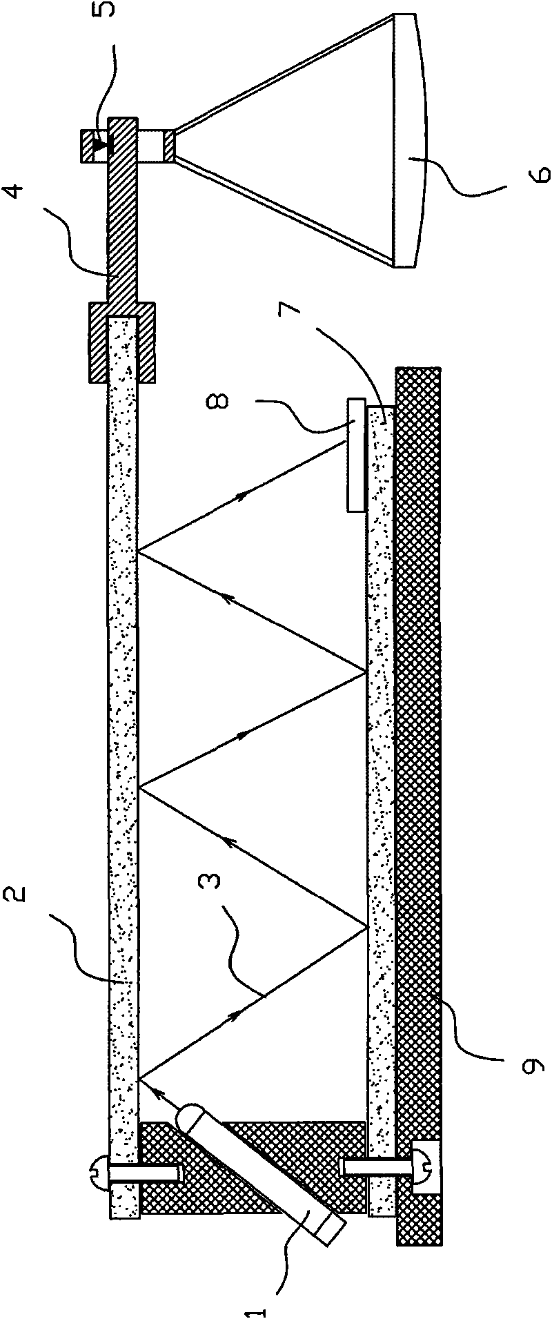
[0016] see figure 1 , the structure of the embodiment is: on a horizontal surface of the base 9, a quartz glass strip with a silver mirror on the upper surface is pasted as the reflector 7; Quartz glass strip --- the upper glass strip 2, there is a certain interval between the two glass strips, the upper glass strip 2 is used as a deformation element, one end is fixed on the base 9, and the other end is suspended with a weighing pan 6.

[0017] The silver mirror of reflector 7 is plated on the upper surface, and the silver mirror of upper glass strip 2 is plated on the lower surface, rather than the structure like ordinary glass mirror, it is for the laser beam to reflect directly on the surface, preventing the reflection of light on the glass surface from causing Interfering light spots.

[0018] The base 9 is equipped with a laser transmitter 1, which emits a laser beam 3 to the lower surface of the glass strip 2 on the deformation element at a fixed inclination angle. The ...


PUM


Abstract

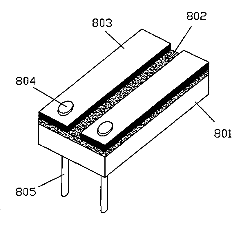
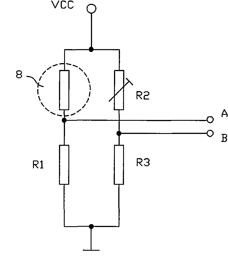
The invention provides a laser photoelectric analytical balance, which is characterized in that two quartz glass trips with silver mirrors coated on the surfaces are parallel up and down; one laser transmitter transmits laser beams to the lower surface of the upper glass strip of a deformation element at a fixed inclination angle and the laser beams are reflected multiple times between the two mirror surfaces of the upper and lower glass strips; a light spot position sensor is arranged at the falling point of the laser beams after multiple times of reflection and is connected in an electrical bridge as a variable resistor; the two output ends of the electrical bridge are connected at the input interface of a measuring and amplifying circuit in a current electrical balance. When the pressure on the upper glass strip changes, deformation change leads to corresponding change of the angles of the reflected laser beams, after multiple times of reflection, accumulation and reinforcement, the light spot position sensor outputs corresponding resistance and the resistance is processed by the measuring and amplifying circuit, thereby realizing weighing. The analytical balance has the advantages of good linearity, high sensitivity and electromagnetic interference resistance.

Description

technical field [0001] The invention relates to a weighing appliance, which is an analytical balance. Background technique [0002] The sensor of the electronic analytical balance adopts a strain sensor, which is a single crystal silicon substrate pasted on an alloy aluminum or alloy steel strip, and circuitous P-type or N-type semiconductor resistance strips are diffused on the substrate and connected to form a bridge. Under the action of pressure, the alloy aluminum or alloy steel strip deforms, which drives the deformation of the single crystal silicon substrate. According to the piezoresistive effect of the semiconductor, the resistivity of the resistance strip changes, causing a change in the resistance value. After being introduced into the measurement circuit, its The change of the output voltage reflects the change of the pressure, so as to achieve the purpose of weighing the mass of the object. [0003] Since the single crystal silicon substrate is pasted on the al...

Claims


Application Information

Patent Timeline
Patent Type & Authority Applications(China)
IPC IPC(8): G01G3/12G01D5/30
Inventor 卢能晓
Owner 卢能晓
Learn More