Coupling method for improving blade cooling efficiency and combustion efficiency of interstage/afterburner/channel combustion chambers

A blade cooling and combustion efficiency technology, applied in the combustion method, combustion chamber, continuous combustion chamber, etc., can solve the problems of large exhaust noise and pollution emissions, increased engine fuel consumption, increased exhaust speed, etc. Emission of pollution, improved cooling efficiency, and improved combustion efficiency

Inactive Publication Date: 2010-05-19
BEIHANG UNIV
View PDF0 Cites 10 Cited by
  • Summary
  • Abstract
  • Description
  • Claims
  • Application Information

AI Technical Summary

Problems solved by technology

The afterburner is used to enable the aircraft to fly at supersonic speed. However, when the afterburner is turned on, the fuel consumption rate of the engine not only increases sharply, but also the exhaust noise and pollution emissions are very large due to the increased exhaust velocity and low combustion efficiency.

Method used


Image

  • Coupling method for improving blade cooling efficiency and combustion efficiency of interstage/afterburner/channel combustion chambers
  • Coupling method for improving blade cooling efficiency and combustion efficiency of interstage/afterburner/channel combustion chambers
  • Coupling method for improving blade cooling efficiency and combustion efficiency of interstage/afterburner/channel combustion chambers

Examples


Embodiment 1

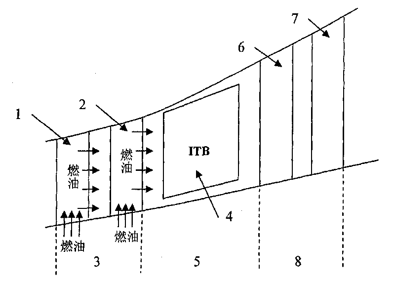
[0029] Embodiment 1: The implementation process for improving the cooling efficiency of the blades of the high-pressure turbine 3 and the combustion efficiency of the turbine interstage combustion chamber (ITB) 4 .

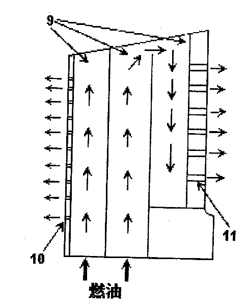
[0030] Such as figure 2 As shown, the high-pressure turbine 3 includes a high-pressure turbine vane 1 and a high-pressure turbine bucket 2 , and the low-pressure turbine 8 includes a low-pressure turbine vane 6 and a low-pressure turbine bucket 7 . Between the high-pressure turbine 3 and the low-pressure turbine 8 is a transition section 5 , in which the turbine interstage secondary combustion chamber (ITB) 4 is located. Figure 3a and Figure 3b It is a schematic diagram of the cooling structure in the blade, since it is a schematic diagram, so Figure 3a and Figure 3b The blades shown may be turbine blades (high-pressure turbine vane 1 or high-pressure turbine blade 2 ), or other blades such as strut blades 12 . The implementation process of the present in...

Embodiment 2

[0038] Embodiment 2: The implementation process for improving the cooling efficiency of the afterburner front strut blade 12 and the combustion efficiency of the afterburner 13 .

[0039] Such as Figure 4 The strut vanes 12 are located in front of the afterburner 13 as shown. Since the cooling structure of the strut blade 12 is similar to that of the turbine blade in Embodiment 1, it is also used here Figure 3a and Figure 3b A schematic diagram of the cooling structure of the strut blade. The implementation process of the present invention is: introduce a certain amount of pressurized fuel oil from the engine fuel system, and then pass the fuel oil into the blade 12 of the support plate. Such as Figure 3a As shown, the fuel oil flows into the cooling channel 9 after being introduced into the blade. When the fuel oil flows through the cooling channel 9, it conducts convective heat exchange with the blades, and cools the blades along the way. As the fuel absorbs the he...

Embodiment 3

[0047] Embodiment 3: The implementation process for improving the cooling efficiency of the high-pressure turbine guide vane 1 and the combustion efficiency of the channel combustor 14 .

[0048] Such as Figure 5 As shown, the channel combustor 14 is located in the channel of the high-pressure turbine vane 1 . The implementation process of the present invention is: introduce a certain amount of pressurized fuel oil from the engine fuel system, and then pass the fuel oil into the high-pressure turbine guide vane 1 blade. Such as Figure 3a As shown, the fuel oil flows into the cooling channel 9 after being introduced into the blade. When the fuel oil flows through the cooling channel 9, it conducts convective heat exchange with the blades, and cools the blades along the way. As the fuel absorbs the heat conducted by the blades, the temperature will rise. The fuel oil can be phase-changed into oil vapor in the internal cooling channel 9 of the blade, and flow out from the a...


PUM


Abstract

The invention provides a coupling method for improving blade cooling efficiency and combustion efficiency of combustion chambers. Blades are turbine blades or front support plate blades of afterburners, and combustion chambers are turbine interstage combustion sub-chambers, afterburners or channel inside combustion chambers. The blades are cooled through fuel, namely introducing the fuel into theblades; the fuel is subjected to convective heat exchange with the blades when flowing through cooling channels inside the blades; the fuel absorbs heat conducted by the blades; temperature is raised; and the fuel undergoes phase change, turns into a gas state, namely oil vapor, and flows out from gas film holes or splitting seams on the surfaces of the blades; or supercritical fuel is formed, sprayed out from the gas film holes or the splitting seams of the blades and rapidly atomized. The oil vapor or the atomized fuel is mixed with high-temperature gas in the channels after entering the blade channels to form mixture gas, and the mixture gas is introduced into the combustion chamber and ignited for combustion. The method can improve not only the cooling efficiency of the blades but also the combustion efficiency of the combustion chambers.

Description

technical field [0001] The invention relates to a coupling method for simultaneously improving blade cooling efficiency and interstage / afterburner / channel combustor combustion efficiency, in particular to simultaneously improving blade cooling efficiency and interstage / afterburner / channel combustor combustion efficiency in aeroengines or gas turbines coupling method. Background technique [0002] With the rapid development of modern aero-engines, in pursuit of high thrust-to-weight ratio and high thermal efficiency, the inlet temperature of modern advanced turbines is getting higher and higher. The turbine inlet temperature of engines with a thrust-to-weight ratio of 7-8 used by the third-generation fighters has reached 1600-1700K, while the turbine inlet temperature of engines with a thrust-to-weight ratio of 10 used by fourth-generation fighters has reached 1900-2000K. In the "Integrated High Performance Turbine Engine Technology" (Integrated High Performance Turbine Engi...

Claims


Application Information

Patent Timeline
Patent Type & Authority Applications(China)
IPC IPC(8): F01D5/18F23R3/02
Inventor 李宇邹正平徐力平刘火星
Owner BEIHANG UNIV
Why Eureka
Try Eureka