Circulating gasifying and pyrolyzing incinerator system and incinerating method

An incinerator and dry distillation technology, applied in the field of incinerators, can solve the problems of insufficient pyrolysis of cooling tar and oil, inability to complete gasification in a short time, delaying the time of dry distillation and degasification, etc., so as to improve the comprehensive utilization rate and arrange Effect of burning time and reasonable burning time

Active Publication Date: 2010-05-19
邵志军
View PDF3 Cites 1 Cited by
  • Summary
  • Abstract
  • Description
  • Claims
  • Application Information

AI Technical Summary

Problems solved by technology

[0004] (1) The above patent wastes are all placed on the reciprocating grate or on the moving grate when burning, because most of the waste to be burned is muddy (such as asphalt), etc., and has a high viscosity during combustion, so it is better to place it on the reciprocating grate or on the moving grate. Impossible to move at all, often resulting in incomplete combustion of the waste;
[0005] (2) Since the solid combustion zone and the oxygen-free carbonization zone adopt an integrated structure, the waste cannot be completely gasified due to the short time during the carbonization gasification, resulting in the insufficient pyrolysis of the cooling tar and oil contained in the carbonization layer gas;
[0006](3) Due to the integrated structure of the solid combustion zone, anaerobic carbonization zone and gas combustion zone, the solid combustion zone mostly contains cooling tar and oil components after combustion. If there is no secondary combustion and the waste in the retort area is fused together, the retort degasification time will be delayed, resulting in incomplete combustion of the retort

Method used


Image

  • Circulating gasifying and pyrolyzing incinerator system and incinerating method
  • Circulating gasifying and pyrolyzing incinerator system and incinerating method

Examples


Embodiment Construction

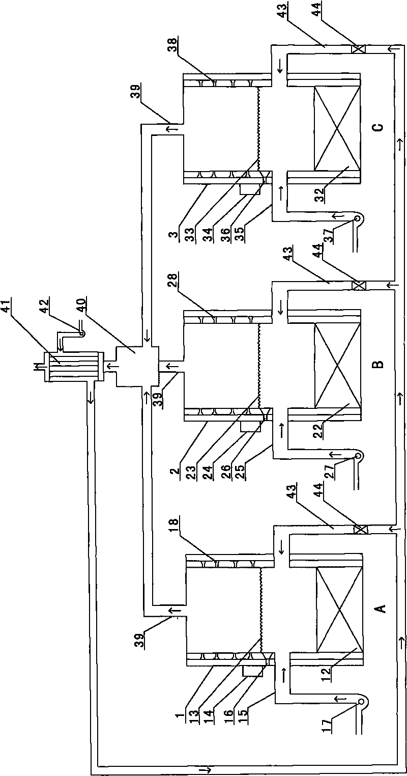
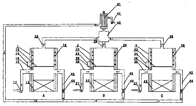
[0016] The circulating gasification dry distillation incinerator is composed of furnace A, furnace B and furnace C, wherein furnace A is equipped with a shell 1, ash removal port 12, fire grate 13, air control system 14, air duct 15, ignition burner 16, Composed of fan A17 and high-pressure air nozzle 18; furnace B is equipped with shell 2, ash outlet 22, grate 23, air control system 24, air duct 25, ignition and combustion aid 26, fan B27, high-pressure air nozzle 28 Composition; C furnace is equipped with shell 3, ash outlet 32, fire grate 33, air control system 34, air duct 35, ignition and combustion aid 36, fan C37, high-pressure air nozzle 38; A furnace, B furnace, C Furnace tops are equipped with tail gas outlet 39, tail gas outlet 39 communicates with secondary combustion chamber 40, secondary combustion chamber 40 communicates with heat exchanger 41, heat exchanger 41 is provided with fan D42, heat exchanger 41 communicates with A furnace, B furnace Furnace C and furn...


PUM


Abstract

The invention discloses a circulating gasifying and pyrolyzing incinerator system and an incinerating method. The circulating gasifying and pyrolyzing incinerator system comprises an incinerator A, an incinerator B and an incinerator C. The incinerating method comprises the following steps: loading the waste material to be incinerated in the shell of the incinerator A; igniting an igniting combustion-supporting device which is arranged at the bottom of the grate of the incinerator A to combust the waste material in a secondary combusting chamber; exchanging the heat with an heat exchanger, and providing the heat for the incinerator B through a heat exchanging pipe; gasifying the waster material to be incinerated in the incinerator B; after the water material in the incinerator A being fully combusted and decomposed, igniting an igniting combustion-supporting device for the incinerator B to combust and decompose the waste material pyrolyzed and gasified in the incinerator B; and pyrolyzing and gasifying the water material in the incinerator C by part of the heat through the heat exchanging pipe. Because the waste materials are pyrolyzed and decomposed due to the circulating combustion by the incinerator A, the incinerator B and the incinerator C, the time and the energy are saved, and the utilization rate of the fuel is improved due to the continuous running of the incinerator A, the incinerator B and the incinerator C in a sealed way. The incinerating method has great popularization value in the field of the circulating gasifying and pyrolyzing incinerator system.

Description

Technical field: [0001] The invention relates to an incinerator, in particular to a circulating gasification dry distillation incinerator and an incineration method for fine-grained, muddy, high-viscosity waste. Background technique: [0002] The types and shapes of solid waste are quite different, such as lumpy and granular waste, muddy sludge, waste with a lot of combustible content, and waste that cannot spontaneously combust and needs to be fueled to support combustion, etc. The form and combustion characteristics of general waste are the main basis for determining the incineration process and its incinerator type. If the waste has a certain shape and can be placed on the grate, and the combustion form is carried out in the form of surface combustion and decomposition combustion, the grate incinerator can be used; but if the waste particles are fine or muddy, If it cannot be placed on the grate, it is necessary to use a hearth type incinerator. However, a large amount ...

Claims


Application Information

Patent Timeline
Patent Type & Authority Applications(China)
IPC IPC(8): F23G5/027F23G5/16F23G5/46
Inventor 邵志军
Owner 邵志军
Why Eureka
Try Eureka