Boost type converter for realizing high-gain voltage multiplication by coupling inductors

A coupled inductance, high gain technology, applied in the field of high gain doubler boost converters, can solve the problems of inability to reduce the voltage stress of the power switch tube, not expanding the gain of the converter, complex coupled inductance structure, etc., and achieve reverse recovery Good characteristics, simple structure, small conduction voltage drop

Active Publication Date: 2010-05-26
HOYMILES POWER ELECTRONICS INC
View PDF0 Cites 29 Cited by
  • Summary
  • Abstract
  • Description
  • Claims
  • Application Information

AI Technical Summary

Problems solved by technology

Although the soft switching circuit can realize the soft switching of the power switching tube, it cannot reduce the voltage stress of the power switching tube, nor does it expand the gain of the converter
There is a method of using switched capacitors to expand the gain of the converter, but this method has an instantaneous current impact, and the number of switched capacitors required to achieve a high output voltage is large and the structure is complicated; there is also a method that uses a three-winding coupled inductor method to realize the expansion of the converter gain, but the structure of the coupling inductor of this method is complicated, which is not conducive to industrial production

Method used


Image

  • Boost type converter for realizing high-gain voltage multiplication by coupling inductors
  • Boost type converter for realizing high-gain voltage multiplication by coupling inductors
  • Boost type converter for realizing high-gain voltage multiplication by coupling inductors

Examples


Embodiment Construction

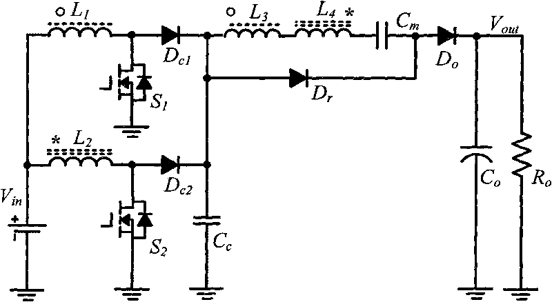
[0021] see figure 1 , the coupled inductor of the present invention implements a high-gain voltage doubler boost converter, including three parts: a Boost voltage booster circuit unit, a voltage doubler circuit unit and an output circuit unit.

[0022] In the Boost circuit unit in the converter, the first winding L 1 The first end and the second winding L 2 The first terminal of the power supply Vin is connected to the positive pole of the power supply Vin, and the first winding L 1 The second terminal of the first switch tube S 1 connected to the drain of the second winding L 2 The second terminal and the second switch tube S 2 connected to the drain of the first switching tube S 1 source and the second switch S 2 The source and the cathode of the power supply Vin are connected, the first clamping diode Dc 1 The anode of the first switching tube S 1 The drain is connected, the second clamping diode Dc 2 The anode of the second switching tube S 2 The drain is connect...


PUM


Abstract

The invention discloses a boost type converter for realizing high-gain voltage multiplication by coupling inductors, comprising two switching tubes, two clamping diodes, a freewheel diode, an output diode, a clamping capacitor, a voltage-multiplying capacitor, an output capacitor and two coupling inductors respectively provided with two windings. The two coupling inductors are utilized to improve the gain of the converter and reduce the voltage stress of the switching tubes and the diodes in the converter, and the leakage inductance of the coupling inductors is utilized to realize the zero current turn-on of the switching tubes and the soft turn-off of the diodes. A clamping circuit consisting of the clamping diodes and the clamping capacitor absorbs a switching tube turn-off voltage spike caused by the leakage inductance and realizes the lossless transfer of energy. A voltage-multiplying circuit is utilized to further improve the gain of the converter and reduce the voltage stress of the switching tubes and the output diode, and staggered parallel connection is utilized to control and reduce ripple waves of input current.

Description

technical field [0001] The invention relates to a DC-DC converter and its application, in particular to a high-gain voltage-doubling and step-up converter realized by coupled inductance. Background technique [0002] In the renewable energy power generation system, since the electric energy generated by many renewable energy sources is low-voltage DC, and the grid-connected power generation system requires a high-voltage DC bus, a DC-DC converter is required to convert the low-voltage DC to High voltage direct current suitable for grid connection. Non-isolated converters with low input current ripple, high gain, and high efficiency play an important role in the field of renewable energy grid-connected power generation. [0003] The output voltage gain of the conventional step-up (Boost) interleaved parallel DC-DC converter is small, and the voltage stress of the power switch tube is relatively large. The recovery current is large, and the reverse recovery loss is large. I...

Claims


Application Information

Patent Timeline
Patent Type & Authority Applications(China)
IPC IPC(8): H02M3/06
Inventor 何湘宁李武华赵一
Owner HOYMILES POWER ELECTRONICS INC
Why Eureka
Try Eureka