Measurement circuit of direct current

A DC current and measurement circuit technology, applied in the direction of measuring electrical variables, measuring current/voltage, measuring devices, etc., can solve the problems of poor thermal stability, large zero drift, measurement error, etc., and achieve good temperature stability and large current range , the effect of high measurement accuracy

Active Publication Date: 2010-06-02
LIBO SHIDAI LITHIUM POWER SCI & TECH BEIJING +1
View PDF0 Cites 7 Cited by
  • Summary
  • Abstract
  • Description
  • Claims
  • Application Information

AI Technical Summary

Problems solved by technology

[0004] However, using a shunt to measure current also has many disadvantages. First, the shunt is connected in series in the main circuit. It will generate heat due to the large current flowing through it, and consume a certain amount of power.
The above example illustrates that a 100A current produces a voltage drop of 75mV on the shunt, and consumes 7.5W of power. This power is emitted in the form of heat, which increases the temperature of the shunt and changes the resistance of the resistor. , causing measurement errors, and the heat-generating shunt may affect the surrounding instruments and equipment, and even cause accidents
Secondly, to measure the voltage of 75mV requires a very high-precision voltmeter, and the cost is high
At present, digital voltmeters are commonly used, and the input voltage is converted into a digital signal by analog-to-digital co

Method used


Image

  • Measurement circuit of direct current
  • Measurement circuit of direct current
  • Measurement circuit of direct current

Examples


Embodiment 1

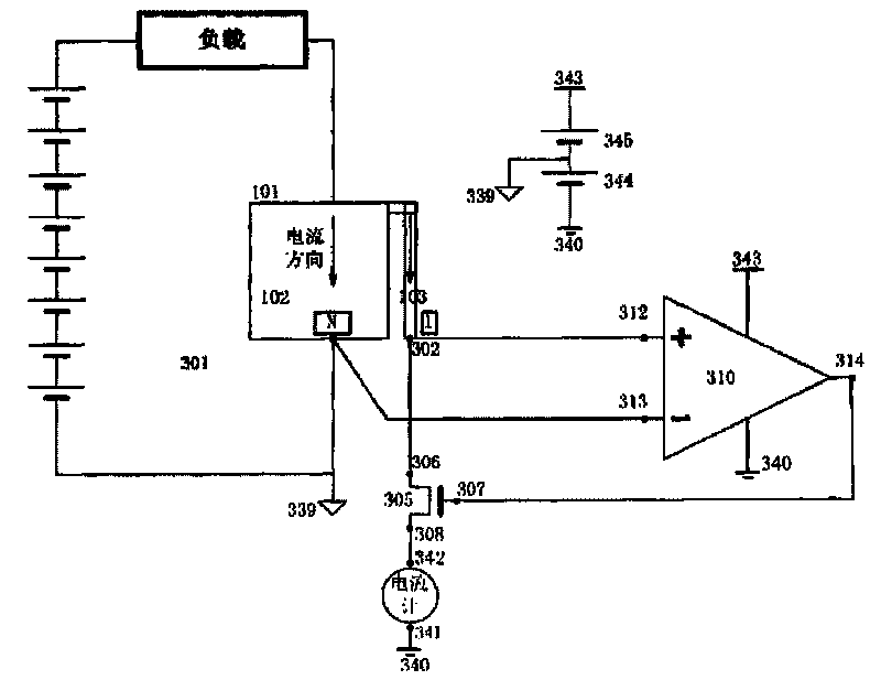
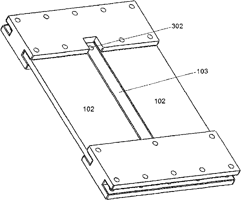
[0044] Such as figure 1 As shown, the direct current detection circuit of this embodiment includes a main circuit 301 of the direct current to be measured. In the direct current measurement circuit, the first conductor 102 is connected in series with the main circuit 301, and one end of the second conductor 103 is connected to the first A conductor 102 is connected, the resistance of the first conductor 102 is smaller than the resistance of the second conductor 103 , and the first conductor 102 and the second conductor 103 form a current conductor 101 with a bifurcated structure.

[0045] The other end 302 of the second conductor 103 is respectively connected to the drain 306 of the first field effect transistor 305 of the direct current measurement circuit and the positive voltage input terminal 312 of the operational amplifier 310;

[0046] The other end of the first conductor 102 is connected to the negative voltage input terminal 313 of the operational amplifier 310 of the...

Embodiment 2

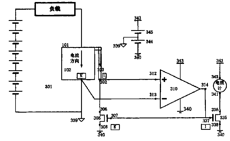
[0061] The second preferred embodiment of the present invention is improved on the basis of the above-mentioned preferred embodiment 1, such as figure 2 As shown, namely:

[0062] The source 308 of the first field effect transistor 305 is connected to the ammeter as the output terminal of the direct current measurement circuit and changed to: connect the grid 307 of the first field effect transistor 305 to the grid 337 of the second field effect transistor 335 connected; the source 338 of the second FET 335 is connected to the ground 340 of the direct current measurement circuit; its drain 336 is connected to one end 341 of the ammeter as the output end of the direct current measurement circuit; the other end of the ammeter 342 is connected to the positive pole 343 of the direct current measurement circuit.

[0063] In this way, the current flowing through the first field effect transistor 305, that is, the current flowing through the second conductor 103, passes through the...


PUM


Abstract

The invention provides a measurement circuit of direct current, comprising a main circuit of the direct current to be measured. In the measurement circuit of direct current, a first conductor is connected with the main circuit in series; one end of a second conductor is connected with the first conductor; the resistance of the first conductor is less than that of the second conductor; the other end of the second conductor is respectively connected with a drain electrode of a first field effect transistor of the measurement circuit of direct current and a positive voltage input end of an operational amplifier; the other end of the first conductor is connected with a negative voltage input end of the operational amplifier of the measurement circuit of direct current; an output end of the operational amplifier is connected with a grid electrode of the first field effect transistor; a source electrode of the first field effect transistor is connected with one end of an amperemeter; and the other end of the amperemeter is connected with the ground of the measurement circuit of direct current. The invention can accurately detect high current, and has low power consumption and large scope of detected current.

Description

technical field [0001] The invention relates to the field of large current measurement, in particular to a direct current measurement circuit. Background technique [0002] DC current measurement has always been a problem to be solved for high power DC powered electrical equipment. By measuring the current, people can know the amount of power consumption, whether the electrical equipment has safety problems such as short circuit and overload, so as to take relevant protective measures to avoid accidents. If the device is powered by a battery, the measurement of the current is directly related to the calculation of the remaining battery capacity, which affects the operation of the device, the use and maintenance of the battery. Therefore, the measurement of DC current, especially the measurement of large current is very important. [0003] The traditional measurement circuit is relatively simple, and generally the shunt is directly connected in series to the main circuit. ...

Claims


Application Information

Patent Timeline
IPC IPC(8): G01R19/00
Inventor 梁伟雄朱恂冯永浩
Owner LIBO SHIDAI LITHIUM POWER SCI & TECH BEIJING
Why Eureka
Try Eureka