Electrical insulator fault detector and detecting method thereof

An insulator and detector technology, applied in the direction of testing dielectric strength, can solve problems such as high risk, difficult on-site measurement, and easy misjudgment, saving manpower and material resources, not being restricted by the environment, and improving work efficiency. Effect

Active Publication Date: 2010-06-02
HENAN HONGBO MEASUREMENT & CONTROL
View PDF0 Cites 18 Cited by
  • Summary
  • Abstract
  • Description
  • Claims
  • Application Information

AI Technical Summary

Problems solved by technology

However, the detection results are easily affected by the viewing angle, and the detection equipment is also expensive
[0015] Each of the above-mentioned detection methods has corresponding problems, such as: the direct observation method has unreliable ground observation, and it needs to go to the tower for detection and it is difficult to find faults in the insulator, such as dendritic channels; the insulator resistance measurement method has problems When measuring, the relative humidity of the air should not be too high, otherwise, it is easy to misjudge
In addition, it is not easy to carry out a large number of detections on transmission lines; the distribution voltage measurement method has the same disadvantages as the measurement of insulation resistance, which needs to be carried out in good weather.
The live contact operation is extremely dangerous; the AC withstand voltage method has the defect that the insulator needs to be replaced and it is difficult to measure on-site; the thermal imager detection of insulator deterioration is greatly affected by temperature changes, and is not suitable for discharges with long gaps. Sensitive issues; the ultraviolet imaging method exists when the conductive carbonized channel is formed on the surface of the insulator, and the partial discharge is required to be operated at night and in a positive temperature environment, which requires that the detection should be carried out in an environment with high humidity or even rainfall, and The detection result is easily affected by the viewing angle, and the detection equipment is also expensive

Method used


Image

  • Electrical insulator fault detector and detecting method thereof
  • Electrical insulator fault detector and detecting method thereof
  • Electrical insulator fault detector and detecting method thereof

Examples


Embodiment 1

[0042] When the distance is 0 meters to detect the fault insulator of 10KV:

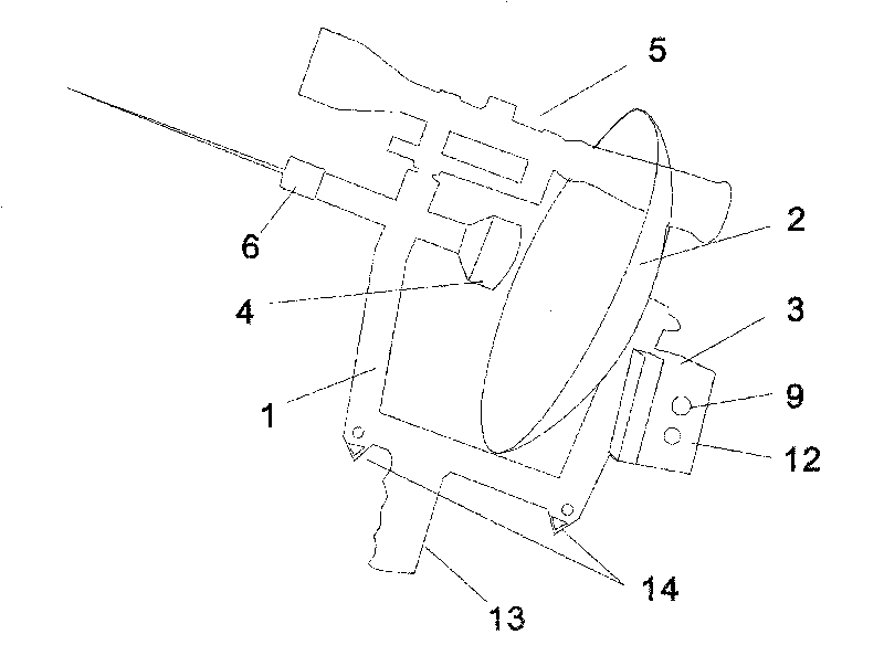
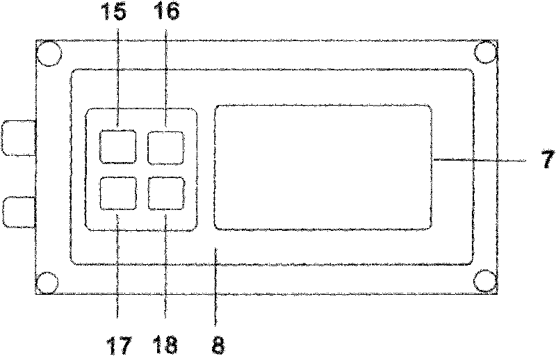
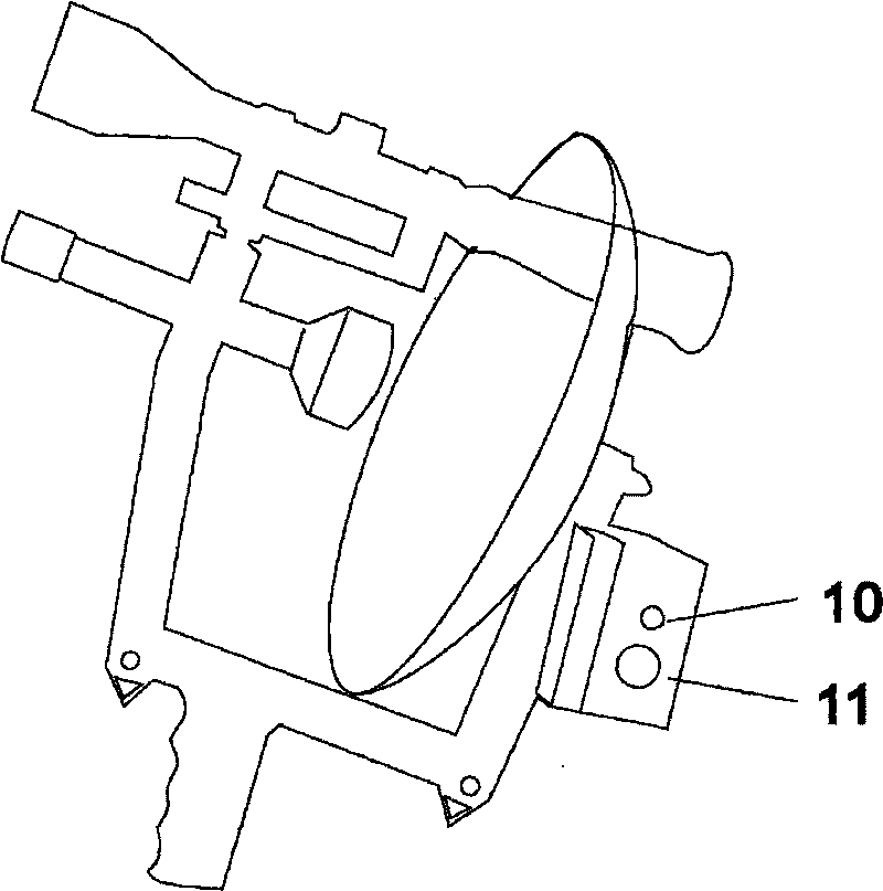
[0043] 1. Insert the earphone into the earphone jack 10, and adjust the sensitivity knob 9 to the maximum. 2. After completing the above step 1, press the power button 15 on the panel 8, adjust the contrast knob 12 to the point where the characters displayed on the LCD screen can be clearly seen, and the hand-held handle 13 is aligned with the insulator to be detected for detection. The detection distance The discharge sound of "click click" appears in the earphone, and the liquid crystal display shows that the intensity is 10, indicating that there is discharge in the insulator; 3. After completing the detection of the above step 2, press the laser 17 button on the panel 8, and the laser beam 6. Locate the discharge point and fault location of the faulty insulator by cooperating with the sight 5; 4. After completing the positioning of the above step 3, when it is detected that the discharge sound of...

Embodiment 2

[0045] When detecting a 35KV faulty insulator at a distance of 20 meters:

[0046] 1. Insert the earphone into the earphone jack 10, and adjust the sensitivity knob 9 to the maximum. 2. After completing the above step 1, press the power button 15 on the panel 8, adjust the contrast knob 12 to the point where the characters displayed on the LCD screen can be clearly seen, and the hand-held handle 13 is aligned with the insulator to be detected for detection. The detection distance The distance is 20 meters; the discharge sound of "click click" appears in the earphone, and the liquid crystal display shows that the intensity is 11, indicating that the insulator has discharge; 3. After completing the detection of the above step 2, press the laser 17 button on the panel 8, and the laser beam 6. Locate the discharge point and fault location of the faulty insulator by cooperating with the sight 5; 4. After completing the positioning of the above step 3, when it is detected that the d...

Embodiment 3

[0048] When detecting 110KV faulty insulators at a distance of 35 meters:

[0049] 1. Insert the earphone into the earphone jack 10, and adjust the sensitivity knob 9 to the maximum.

[0050] 2. After completing the above step 1, press the power button 15 on the panel 8, adjust the contrast knob 12 to the point where the characters displayed on the LCD screen can be clearly seen, and the hand-held handle 13 is aligned with the insulator to be detected for detection. The detection distance The distance is 35 meters; there is a "click click" discharge sound in the earphone, and the LCD display shows an intensity of 12, indicating that the insulator has a discharge;

[0051] 3. After completing the detection of the above step 2, press the laser 17 button on the panel 8, and the laser beam 6 passes through the collimating mirror 5 to locate the discharge point and fault location of the faulty insulator;

[0052] 4. After completing the positioning of the above step 3, when it is ...


PUM


Abstract

The invention belongs to a detecting device for electric equipment, in particular to an electrical insulator fault detector and a detecting method thereof which can be applied to the local discharge detection for electric equipment, the discharge detection for corona and the discharge detection for a high-pressure switch. The detector comprises a main bracket, an ocular lens and a laser which are installed on the main bracket, a sensor which is installed behind the laser, and a wave collector which is fixed on the main bracket behind the sensor. The sensor is connected with a host machine of a micro-computer. The host machine of the micro-computer is connected with the laser via power lines. A liquid crystal display is installed on the host machine of the micro-computer. The invention has simple, convenient and safe operation, can be operated remotely without cutting off power supply, decreases the labor intensity and promotes the working efficiency. The invention is mainly applied to remote detection for electrical insulator high-pressure lines and power supply devices, in order to avoid detecting via climbing electric pole one by one and save the labor and material resources.

Description

technical field [0001] The invention belongs to an electrical equipment detection device, and in particular relates to an insulator fault detector and a detection method that can be applied to electrical equipment partial discharge detection, corona discharge detection and high-voltage switch discharge detection. Background technique [0002] From the analysis of the deterioration characteristics and causes of insulators, it can be seen that there are differences between the deteriorated insulators and the good insulators in many aspects such as electrical performance, partial discharge, and temperature distribution. Based on these characteristics and differences, corresponding instruments or devices have been developed, and different measurement methods have been studied. Judging from the current detection methods, there are live detection and power failure detection; there are contact detection and non-contact detection. From the basis of the measurement method, there are...

Claims


Application Information

Patent Timeline
Patent Type & Authority Applications(China)
IPC IPC(8): G01R31/12
Inventor 郑新才卜祥洲陈涛吴国华曹海军卜永豪马小庆
Owner HENAN HONGBO MEASUREMENT & CONTROL
Why Eureka
Try Eureka