Unlock instant, AI-driven research and patent intelligence for your innovation.

Isothermal low temperature co-shift reactor

A reactor and low-temperature technology, applied in chemical instruments and methods, inorganic chemistry, non-metallic elements, etc., can solve the problems of difficult operation and control, burnout catalyst, and large steam loss, so as to reduce steam consumption and gas resistance , the effect of low water vapor ratio

Active Publication Date: 2011-12-21
HUNAN ANCHUN ADVANCED TECH
View PDF3 Cites 1 Cited by
  • Summary
  • Abstract
  • Description
  • Claims
  • Application Information

AI Technical Summary

Problems solved by technology

[0033] The second type of typical transformation process has three transformation furnaces, two of which are respectively connected with water spray humidification towers, with a large number of equipment, a long process, and a large area; There are many regulating valves (control points) in the sub-line of condensate cooling and shock, and the operation is difficult
[0034] The third typical conversion process can only deal with the conversion of gas with a CO content of about 30%. A conversion furnace contains three-stage catalysts, which are connected with an external cooling heat exchanger and two water spray cooling and superheating devices, with three inputs and three outputs. The pipeline is complex and the temperature adjustment is difficult
[0036] In short, the above three typical conversion processes require many conversion devices, long processes, large steam loss, and difficult operation and control.
Especially the first furnace (section) is easy to overheat and burn out the catalyst

Method used


Image

  • Isothermal low temperature co-shift reactor
  • Isothermal low temperature co-shift reactor
  • Isothermal low temperature co-shift reactor

Examples


Embodiment Construction

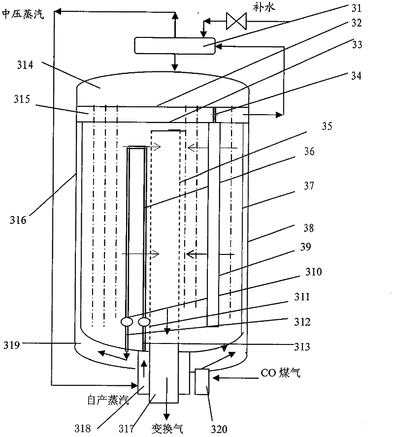
[0078] There are two inner ring steam inlet pipes 313 and two outer ring pipes 310 .

[0079] The flow of gas in the isothermal low-temperature CO shift reactor is as follows: the preheated unreacted gas enters the bottom of the annulus between the radial basket (37) and the cylindrical shell (38), mixes with superheated steam, and flows along the annulus. Gap rises, passes through the small holes of the radial basket 37, and enters the catalytic bed uniformly and radially for reaction. After the reaction, the gas is collected in the central tube 35 and flows out of the reactor from top to bottom;

[0080] The flow of water vapor in the isothermal and low-temperature CO shift reactor is as follows: feed water is added to the steam drum 31, mixed with the water in the steam drum, and then enters the water chamber 314 of the isothermal and low-temperature CO shift reactor through the downcomer, and flows evenly into multiple heat exchange tubes 39 , is heated by the reaction hot...


PUM


Abstract

An isothermal low-temperature CO shift reactor, which is a reaction device for converting CO and water vapor into CO2 and H2 at a certain constant low temperature, including a radial basket, a steam chamber, and a water chamber in a cylindrical shell, and a central tube Catalysts are filled in the radial baskets to form a catalytic bed; there are multiple suspended heat exchange tubes in the catalytic bed and there is water in the tubes. ; An inverted U-shaped pipe is also provided in the catalytic bed, and its two ports are respectively connected with two concentric annular pipes. One annular pipe is connected with the steam outlet of the steam drum through the connecting pipe and the steam inlet; the other annular pipe is connected with the steam drum through the corresponding connecting pipe. The annular gap between the cylindrical shell and the radial basket is communicated, and the unreacted gas inlet is also communicated with the annular gap; the water outlet of the steam drum is connected with the water chamber, and the steam outlet of the steam chamber is connected with the steam inlet of the steam drum. It can continuously release heat during the reaction and continuously use another medium to remove the heat of reaction, so as to maintain the reaction at low temperature and constant temperature.

Description

technical field [0001] The invention relates to a method for converting CO and water vapor into CO at a certain constant low temperature 2 with H 2 The reaction equipment, the application of gas containing a large amount of CO into H 2 , and further used as a hydrogen source for synthetic ammonia, methanol, acetic acid and other products. Background technique [0002] Coal gas, natural gas reformed gas, coke oven gas reformed gas, calcium carbide furnace tail gas, blast furnace gas, etc., all of these gases contain a large amount of CO, for example, calcium carbide tail gas contains 90% CO, and the CO content in coal gas is 30% to 68% (with gas different methods), CO can be transformed into useful H 2 , the transformed reaction is: [0003] [0004] The conversion reaction is an exothermic reversible reaction, there must be a catalyst and an excess of H 2 O (water vapor) is excessive according to the reaction formula, in order to make the reaction to generate H 2 di...

Claims


Application Information

Patent Timeline
Patent Type & Authority Patents(China)
IPC IPC(8): B01J8/02C01B3/16
Inventor 谢定中
Owner HUNAN ANCHUN ADVANCED TECH