
Device and method for processing roller micro groove

A processing device and processing method technology, applied in metal processing equipment, tool clips, manufacturing tools and other directions, can solve the problems of increasing the cost of roller manufacturing, affecting the manufacture of optical brightness enhancement films, and being unfavorable for mass production.

Inactive Publication Date: 2010-06-09
INNOLUX CORP
View PDF11 Cites 8 Cited by
  • Summary
  • Abstract
  • Description
  • Claims
  • Application Information

AI Technical Summary

Problems solved by technology

[0006] In the traditional manufacturing technology, a single tool is used to cut micro-grooves on the surface of the roller. However, in the face of an increasing number of micro-grooves, not only the processing time cannot be reduced, but the wear rate of the diamond tool is also greatly increased.
Therefore, it is not only unfavorable for mass production, but also leads to an increase in the production cost of the roller.
Moreover, due to the rapid wear of the diamond cutter, the uniformity of the micro-groove structure on the surface of the roller will be affected, which in turn will affect the production of the optical brightness enhancement film.

Method used


Image

  • Device and method for processing roller micro groove
  • Device and method for processing roller micro groove
  • Device and method for processing roller micro groove

Examples


Embodiment Construction

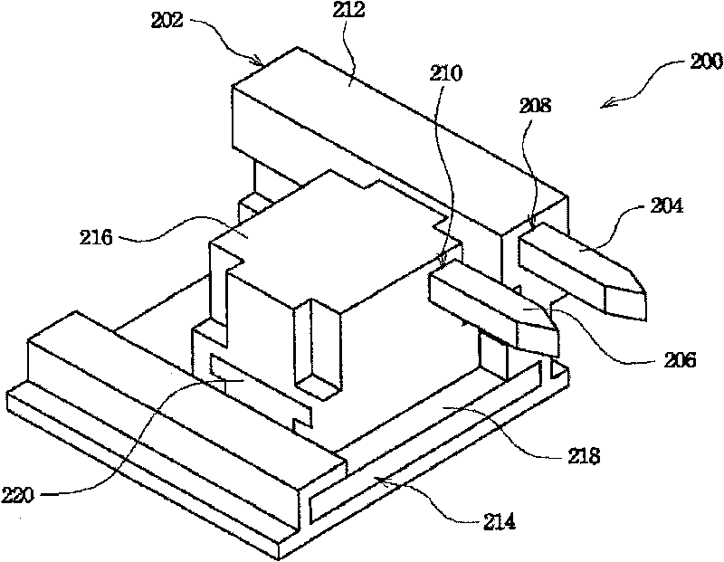
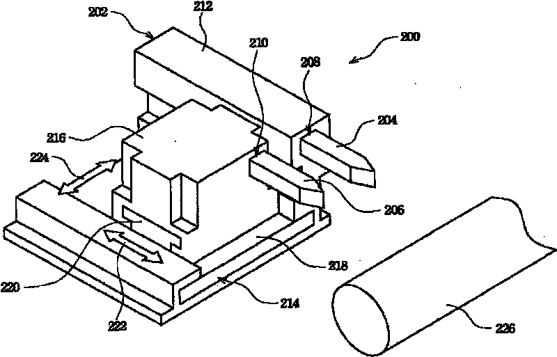
[0034] The invention discloses a processing device and a processing method for micro grooves of a roller. In order to make the narration of the present invention more detailed and complete, refer to the following description and cooperate Figure 2 to Figure 4 attached drawings.

[0035] Please refer to figure 2 , which is a three-dimensional schematic diagram illustrating a roller micro-groove processing device according to a preferred embodiment of the present invention. In an exemplary embodiment, the roller micro-groove processing device 200 can be used on a roller 226 (please refer to image 3 ) to define a micro-groove structure by cutting on the surface, wherein the roller 226 can be an optical film processing roller for making an optical film, such as an optical brightness enhancement film. The roller microgroove processing device 200 mainly includes a tool holder 202 and at least two tools, such as a rough turning tool 204 and a finishing turning tool 206 , wherei...


PUM


Abstract

The invention discloses a device and a method for processing a roller micro groove. The device for processing the roller micro groove at least comprises: a cutter holder, wherein one side of the tool holder is at least provided with a plurality of cutter fixing openings; and a plurality of cutters which are fixedly arranged in the cutter fixing openings in a corresponding manner, wherein each cutter is provided with a knifing and a nose radius, the knifings are different from each other and the same goes for the nose radii, and these cutters can cut the surface of a roller simultaneously.

Description

technical field [0001] The invention relates to a processing device and a processing method of a roller, and in particular to a processing device and a processing method of a micro-groove of a roller. Background technique [0002] In the development of flat panel displays, the enlargement of display size is one of the important trends. Therefore, in response to the large-scale development of flat-panel displays, the manufacturing technology of large-scale backlight modules that provide backlight sources for display panels has also become the focus of research and development. [0003] In the backlight module of the liquid crystal display, the optical brightness enhancement film (Brightness Enhancement Film; BEF), commonly known as the prism sheet, is a very important component in the backlight module of today. However, the optical brightness enhancement film is quite expensive. In a backlight module, the cost of the optical brightness enhancement film accounts for about 40%...

Claims


Application Information

Patent Timeline
IPC IPC(8): B23B5/48B23B29/26
Inventor 廖运炫
Owner INNOLUX CORP
Learn More