Supercharge Your Innovation With Domain-Expert AI Agents!

Method for preparing activated carbon activated by combining flue gas and water vapor in stokehole

A composite activation, activated carbon furnace technology, applied in chemical instruments and methods, inorganic chemistry, carbon compounds, etc., can solve the problems of dispersion, large amount and high cost, and achieve the effect of reducing production cost, high activity and long service life

Inactive Publication Date: 2010-06-09
HARBIN INST OF TECH
View PDF0 Cites 9 Cited by
  • Summary
  • Abstract
  • Description
  • Claims
  • Application Information

AI Technical Summary

Problems solved by technology

[0004] The technical problem to be solved by the present invention is to solve the problem of high cost of using activated carbon material desulfurization adsorbent for small and medium-sized coal-fired boilers with large and dispersed existing enterprises and limited economic capacity of the affiliated enterprises. Pre-furnace preparation method of activated carbon

Method used


Image

  • Method for preparing activated carbon activated by combining flue gas and water vapor in stokehole
  • Method for preparing activated carbon activated by combining flue gas and water vapor in stokehole

Examples


specific Embodiment approach 1

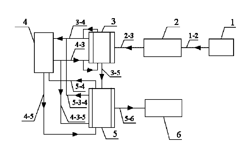
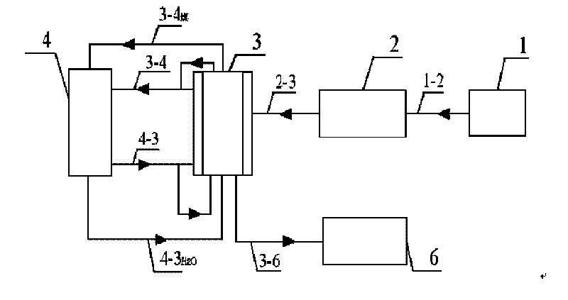
[0015] Specific implementation mode one: combine figure 1 In this embodiment, the activated carbon furnace preparation method of flue gas and water vapor combined activation is realized according to the following steps: 1. The raw coal is sent from the raw coal storage bin 1 to the raw coal crushing and screening chamber 2 via the conveyor belt 1-2, and after screening The raw coal particles with a particle size of 3-5 mm enter the carbonization furnace 3 for carbonization through the raw coal particle conveying belt 2-3, and the high-temperature hot flue gas drawn from the boiler 4 supplies heat for the carbonization furnace 3, and the heating flue gas circuit of the carbonization furnace 3 It consists of a boiler 4, a carbonization furnace hot flue gas pipeline 4-3, an outer heating layer of the carbonization furnace 3, and a boiler hot flue gas pipeline 3-4, and a bypass is provided on the carbonization furnace hot flue gas pipeline 4-3 A stream of hot flue gas is used as a...

specific Embodiment approach 2

[0016] Specific embodiment 2: The difference between this embodiment and specific embodiment 1 is that the amount of hot flue gas purged per 1 kg of raw coal particles in step 1 is 0.03 Nm 3 / h~0.05Nm 3 / h. Others are the same as in the first embodiment.

specific Embodiment approach 3

[0017] Embodiment 3: This embodiment differs from Embodiment 1 or Embodiment 2 in that the activation loss on ignition of the water vapor described in step 2 is 45% to 50%. Others are the same as in the first or second embodiment.


PUM


Abstract

The invention provides a method for preparing activated carbon activated by combining flue gas and water vapor in a stokehole, and relates to the method for preparing flue gas desulfurization activated carbon with medium and small-capacity coal-fired boilers. The method solves the problem that activated carbon material desulfurization adsorbents adopted by a great number of traditional disperse small and medium-sized coal-fired boilers having limited economic capabilities of membership enterprises have high cost. The method comprises the following steps of: using hot flue gas extracted from the boilers to supply heat, and purging raw coal particles at the temperature of between 200 and 250 DEG C, 350 and 400 DEG C, and 500 and 600 DEG C respectively; carbonizing for 0.5 to 1.5 h at the temperature of between 600 and 800 DEG C to obtain a carbonized material; and activating the carbonized material by using the water vapor extracted from the boilers to obtain the activated carbon. In the method, the hot flue gas extracted from the boilers is used to supply heat to the carbonization and activation processes in the process of preparing the activated carbon and manufacture more micropore points in the carbonization process, then is treated with tail gases of the boilers together after finishing the action, so that additional fuel combustion equipment and gas processing equipment are saved, and the production cost is reduced.

Description

technical field [0001] The invention relates to a method for preparing activated carbon for flue gas desulfurization in front of a small and medium capacity coal-fired boiler. Background technique [0002] The use of activated carbon materials for flue gas pollution control is rapidly developing due to its advantages of high efficiency, low water consumption, recyclable by-products, and no waste. In the production process of activated carbon materials for flue gas desulfurization, there are generally five processes including coal preparation, molding, carbonization, activation, and finished product treatment. The columnar activated carbon used in flue gas desulfurization needs to grind the raw coal to a certain fineness before molding, and then carbonize and activate after air drying. The carbonization and activation process requires high-temperature gas heating, and the high-temperature heating gas and the gas generated during carbonization and thermal decomposition of mat...

Claims


Application Information

Patent Timeline
IPC IPC(8): C01B31/10C01B32/336
Inventor 高继慧朱玉雯高建民杜谦吴少华秦裕琨
Owner HARBIN INST OF TECH
Features
  • R&D
  • Intellectual Property
  • Life Sciences
  • Materials
  • Tech Scout
  • Unparalleled Data Quality
  • Higher Quality Content
  • 60% Fewer Hallucinations
Learn More