Thermo-acoustic refrigerator device driven by cascade thermo-acoustic engine

A thermoacoustic engine and thermoacoustic refrigerator technology, applied in refrigerators, refrigeration and liquefaction, lighting and heating equipment, etc., can solve the problems that restrict the wide application of thermally driven thermoacoustic refrigerators, it is difficult to overcome the sound DC loss, and the system efficiency is affected. and other problems, to avoid the loss of acoustic circulation, improve the actual efficiency, and achieve the effect of high-efficiency thermoacoustic conversion.

Inactive Publication Date: 2010-06-09
BEIJING INSTITUTE OF TECHNOLOGYGY
View PDF0 Cites 7 Cited by
  • Summary
  • Abstract
  • Description
  • Claims
  • Application Information

AI Technical Summary

Problems solved by technology

In addition, traveling-wave thermoacoustic refrigerators arranged in a ring are always difficult to overcome the problem of acoustic direct current loss, which reduces the cooling efficiency.
The matching between various types of thermoacoustic engines and traveling wave refrigerators also affects the impr

Method used


Image

  • Thermo-acoustic refrigerator device driven by cascade thermo-acoustic engine
  • Thermo-acoustic refrigerator device driven by cascade thermo-acoustic engine
  • Thermo-acoustic refrigerator device driven by cascade thermo-acoustic engine

Examples


Embodiment 1

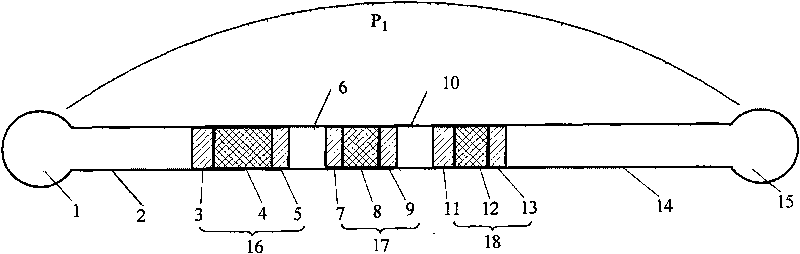
[0032] The structure of this embodiment is as figure 1 shown, where P 1 It is the oscillation pressure amplitude, which includes the engine-level terminal resonant cavity 1, the engine-level resonant tube 2, and the standing wave-level engine unit 16 connected in sequence (including: room temperature end cooler 3, regenerator 4, high temperature end heater 5) , thermal buffer tube 6 in the standing wave band, engine unit 17 at the traveling standing wave level (comprising: room temperature side cooler 7, regenerator 8, high temperature side heater 9), thermal buffer tube 10 in the traveling band band, and traveling standing wave level refrigerator unit 18 (including: room temperature end cooler 11 , regenerator 12 , low temperature end heat exchanger 13 ), refrigerator-level resonance tube 14 and refrigerator-level terminal resonance cavity 15 .

[0033] In this embodiment, the sound work is initially generated in the thermoacoustic unit 16 working under the standing wave mec...

Embodiment 2

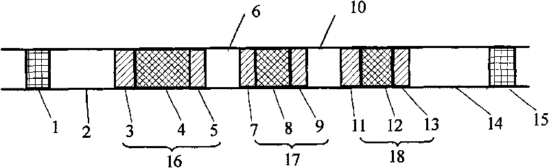
[0039] The structure of this embodiment is as figure 2 As shown, it includes sequentially connected engine-level moving piston 1, engine-level resonant tube 2, standing-wave-level engine unit 16 (comprising: room temperature end cooler 3, regenerator 4, high-temperature end heater 5), standing wave section heat sink Buffer tube 6, traveling standing wave engine unit 17 (including: room temperature end cooler 7, regenerator 8, high temperature end heater 9), traveling wave heat buffer pipe 10, traveling standing wave refrigerator unit 18 (including: Room temperature end cooler 11 , regenerator 12 , low temperature end heat exchanger 13 ), refrigerating machine level resonant tube 14 and refrigerating machine level moving piston 15 .

[0040] In this embodiment, by adjusting the working frequency and phase angle relationship between the moving piston 1 of the engine stage and the moving piston 15 of the refrigerator stage, the boundary conditions of the sound field in the syste...

Embodiment 3

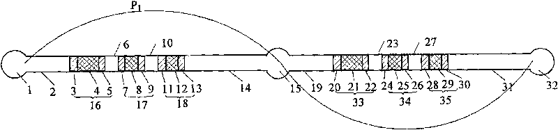
[0046] The structure of this embodiment is as image 3 shown, where P 1 is the amplitude of the oscillating pressure, which includes a first-level engine-level terminal resonant cavity 1, a first-level engine-level resonant tube 2, and a standing-wave level engine unit 16 (including: room temperature end cooler 3, regenerator 4, Heater 5 at the high temperature end, heat buffer tube 6 for the first-stage standing wave band, engine unit 17 for the first-stage traveling standing wave stage (including: room temperature end cooler 7, regenerator 8, high-temperature end heater 9), first-stage traveling wave band Thermal buffer tube 10, primary standing wave refrigerator unit 18 (including: room temperature end cooler 11, regenerator 12, low temperature end heat exchanger 13), primary refrigerator stage resonant tube 14, resonant cavity 15, Secondary engine level resonance tube 19, secondary standing wave level engine unit 33 (including: room temperature end cooler 20, regenerator ...


PUM


Abstract

The invention relates to a thermo-acoustic refrigerator device driven by a cascade thermo-acoustic engine, comprising an engine stage terminal resonant cavity, an engine stage resonatron, a standing wave stage engine unit, a standing wave section thermal buffer tube, a moving standing wave stage engine unit, a moving standing wave section thermal buffer tube, a moving standing wave stage refrigerator unit, a refrigerator stage resonatron and a refrigerator stage terminal resonant cavity. The invention comprehensively utilizes two mechanisms of thermo-acoustic conversion, so that the thermo-acoustic effects generated by both travelling wave component and standing wave component of sound wave in the moving standing wave stage engine unit are thermal acoustic effects and in the moving standing wave stage refrigerator are pumping thermal effect. The device uses linear arrangement to avoid acoustic circulation loss and simplify the system structure and adopts a two-stage or multistage engine unit to improve the sound energy density, effectively improve the cooling density and decrease the cooling temperature, thereby compacting the system structure.

Description

field of invention [0001] The invention relates to a refrigerator device, in particular to a cascaded thermoacoustic engine-driven thermoacoustic refrigerator device. Background technique [0002] The thermoacoustic engine uses the thermoacoustic effect to convert heat energy into sound energy, and the generated sound energy can be used to drive a pulse tube refrigerator or other forms of thermoacoustic refrigerators. The combination of the two is called a thermoacoustic-driven refrigeration system. It has three main advantages: first, the system has no mechanical moving parts, simple structure, low manufacturing cost, and high reliability; second, the working medium is an environmentally friendly gas; third, the system directly uses thermal energy as the driving source, and is expected to Applied to the abundant and scarce thermal energy resources [0003] It has a wide application prospect especially in remote areas and offshore oilfield natural gas liquefaction. [0004...

Claims


Application Information

Patent Timeline
IPC IPC(8): F25B23/00
Inventor 康慧芳郑宏飞
Owner BEIJING INSTITUTE OF TECHNOLOGYGY
Why Eureka
Try Eureka