Optical synchronizing signal labeling system for optical diagnosis of combustion system of internal-combustion engine

A technology of combustion system and marking system, which is applied in the field of laboratory equipment, can solve problems such as errors, accumulated errors, and inconvenient use, and achieve the effects of cost saving, obvious adjustment effect, and low price

Inactive Publication Date: 2010-06-09
TSINGHUA UNIV
View PDF0 Cites 5 Cited by
  • Summary
  • Abstract
  • Description
  • Claims
  • Application Information

AI Technical Summary

Problems solved by technology

The traditional method is to directly record the working time and crankshaft signal of the photoelectric system from a certain base point, but this process requires equipment to support, and the timing and system delay of each equipment must be accurately calculated. In addition, there are cumulative errors in computer sampling timing. so inconvenient to use
The current solution is to install an electrical signal generating device at the flywheel of the engine, and then drive the light-emitting diode to flash at the compression top dead center. This system can obtain the compression top dead center mark d

Method used


Image

  • Optical synchronizing signal labeling system for optical diagnosis of combustion system of internal-combustion engine
  • Optical synchronizing signal labeling system for optical diagnosis of combustion system of internal-combustion engine
  • Optical synchronizing signal labeling system for optical diagnosis of combustion system of internal-combustion engine

Examples


Embodiment Construction

[0021] The present invention will be described in detail below in conjunction with the accompanying drawings and specific embodiments.

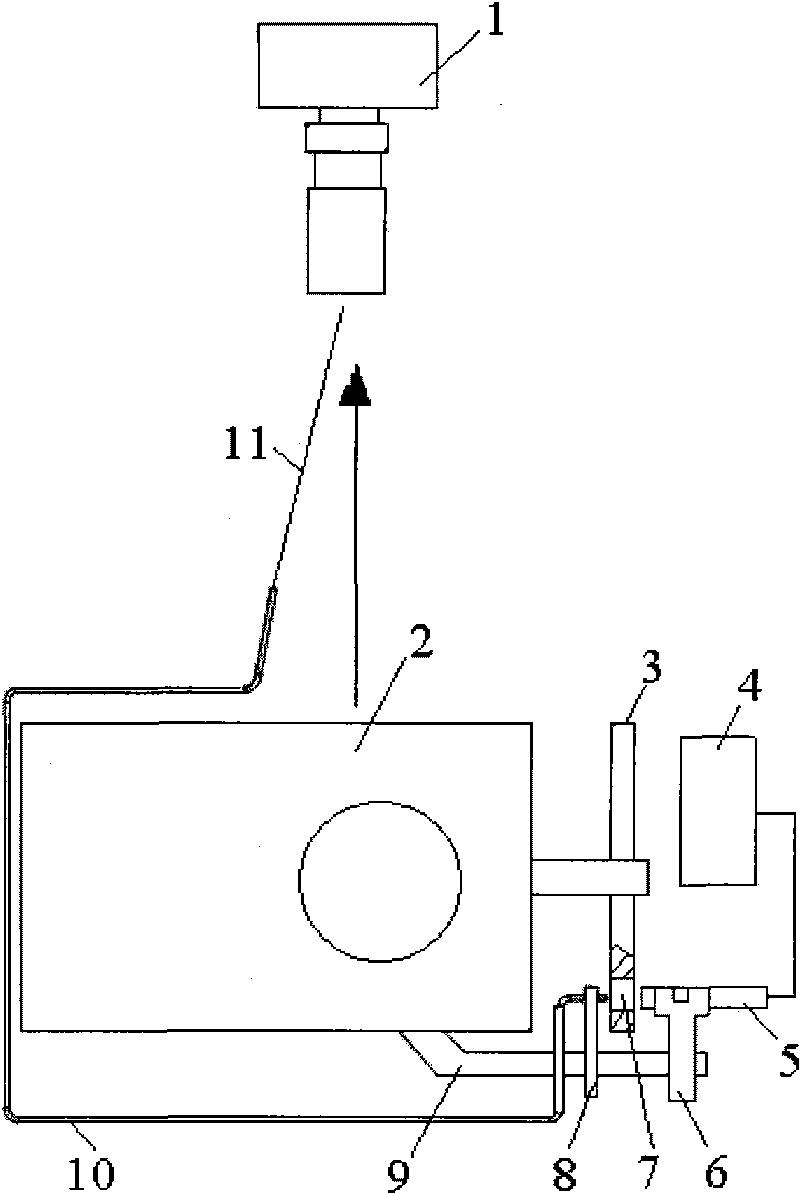
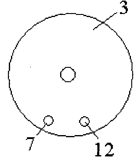
[0022] Such as figure 1 As shown, the structure of the marking system of the present invention includes a marking code wheel 3 , a camera 1 and a bracket 9 . Mark the structure of the code wheel 3, such as figure 2 As shown, the marking code wheel 3 is provided with a first marking hole 7 and a second marking hole 12 respectively, and the central angle between the first marking hole 7 and the second marking hole 12 is 30°. The bracket 9 is respectively provided with a holder 8 and a mounting seat 6, and the holder 8 is provided with a light guide device 10, the laser beam entry end of the light guide device 10 is fixed on the holder 8, and the laser beam output end of the light guide device 10 faces Camera 1, mounting base 6 is provided with laser tube 5, marking code disc 3 is positioned between light guide device 10 laser beam entry end ...


PUM

PropertyMeasurementUnit
Diameteraaaaaaaaaa

Abstract

The invention relates to an optical synchronizing signal labeling system for optical diagnosis of a combustion system of an internal-combustion engine, comprising a labeling code disc, image acquisition equipment and a connection fixing mechanism; a light guide device and a laser tube are respectively arranged on the connection fixing mechanism, the laser beam inlet end of the light guide device and the laser beam transmitting terminal of the laser tube are oppositely arranged, the laser beam output end of the light guide device is toward to the image acquisition equipment, and two labeling holes are arranged on the labeling code disc; the labeling system has simple structure, and has no time-delay problems of circuits and optical-to-electrical conversion, and has no delay of optical signals; under a condition that the rotating speed of the engine caused by combustion is fluctuated instantaneously, accurate correction computation does not need aiming at the rotating speed, so as to ensure the brightness of the optical signals, be convenient for regulation, improve the signal synchronizing precision and the combustion analysis reliability, be suitable for a visual experiment rack of the internal-combustion engine structure which is frequently reconstructed or regulated and have great significance to the visual research in an internal-combustion engine cylinder.

Description

technical field [0001] The invention belongs to the technical field of laboratory equipment, and relates to an image synchronous signal providing device for a visualized optical engine, in particular to an optical synchronous signal marking system for optical diagnosis of an internal combustion engine combustion system. Background technique [0002] The optical diagnosis of internal combustion engine combustion is an important basis for advanced research and development and simulation calculations of internal combustion engines. In the visualization research of the engine cylinder, whether modern optical testing or traditional optical testing is used, the synchronization determination of the optical signal and the crankshaft is an important link in the experiment, and the error in this link directly affects the mixture formation process and combustion phase. Research accuracy, such as a large deviation in the correspondence between the optical signal and the crank angle, wil...

Claims


Application Information

Patent Timeline
IPC IPC(8): G01M15/00G01P3/36
Inventor 王建昕马骁何旭
Owner TSINGHUA UNIV
Why Eureka
Try Eureka