
Radio frequency signal generating device

A technology for generating devices and radio frequency signals, which is applied in the field of radio frequency signal sources, can solve the problems of high price, poor spurious signal suppression ability, complex structure, etc., and achieve the effects of convenient operation, extended frequency output range, and convenient operation

Active Publication Date: 2010-06-09
ウーハン ジョンケ ニウジン マグネティック レゾナンス テクノロジー カンパニー リミテッド
View PDF0 Cites 37 Cited by
  • Summary
  • Abstract
  • Description
  • Claims
  • Application Information

AI Technical Summary

Problems solved by technology

The problem with this structure is that the radio frequency signal synthesizer only provides a wide frequency range adjustable base frequency signal, and other functions are completed using analog quadrature modulation technology, which has a complex structure and spurious Poor signal suppression and expensive

Method used


Image

  • Radio frequency signal generating device
  • Radio frequency signal generating device

Examples


Embodiment 1

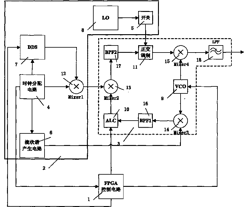
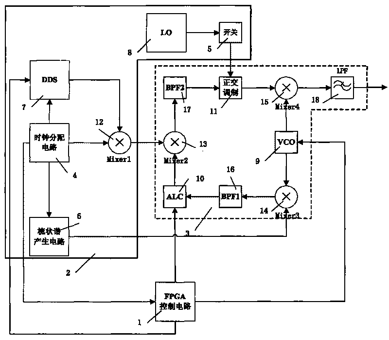
[0027] Attached below figure 1 The present invention is described in further detail:

[0028] according to figure 1 It can be seen that the radio frequency signal source of the nuclear magnetic resonance spectrometer is mainly composed of three parts: the FPGA control circuit 1, the signal generation module 2, and the three-mixer module 3. Wherein the FPGA control circuit 1 realizes the rapid configuration of the direct digital frequency synthesizer (DDS) 7, the reference input adjustment of the automatic level control circuit (ALC) 10, and the tuning voltage control of the voltage-controlled oscillator (VCO) 9; the signal generation module 2 Provide the external clock signal of the FPGA, and provide each input signal of the three-mixing module, such as the local oscillator signal (LO), the comb spectrum signal, and the first mixing by the direct digital frequency synthesizer (DDS) 7 and the clock distribution circuit 4 Mixer (Mixer 1) generates signals by mixing; the three-...


PUM


Abstract

The invention discloses a radio frequency signal generating device. A control circuit is connected with a configuration port of a digital frequency synthesizer, a reference end of an operational amplifier of an automatic level control circuit and a tuning end of a voltage-controlled oscillator; a clock distribution circuit is connected with the digital frequency synthesizer, a frequency mixer and a comb-shaped spectrum generating circuit; the digital frequency synthesizer is connected with the clock distribution circuit and the frequency mixer; a local oscillation signal is connected with a switch; the switch is connected with a local oscillation input port of a quadrature modulating circuit; the output port of the comb-shaped spectrum generating circuit is connected with a third frequency mixer; the voltage-controlled oscillator is connected with the third frequency mixer, the frequency mixer and the control circuit; the frequency mixer is connected with a band-pass filter; the band-pass filter is connected with the automatic level control circuit; the output port of the automatic level control circuit is connected with the frequency mixer; and the frequency mixer is connected with the band-pass filter. The invention has digital control, good generality, low cost, flexible frequency setting and good stray and phase noise performance.

Description

technical field [0001] The present invention relates to the technical field of radio frequency signal sources, more specifically to a radio frequency signal generating device, a digital low-noise radio frequency signal source capable of high-speed frequency switching and amplitude and phase modulation, and the device can also be used for nuclear magnetic resonance spectrometers and Magnetic resonance imager. Background technique [0002] The radio frequency signal source is an essential and important part of the nuclear magnetic resonance instrument. A typical RF signal synthesizer is a frequency synthesizer (Programmable Test Source, PTS), which is mainly composed of a standard frequency module (SGA, SGB), a high frequency resolution generation module (DM, DMA) and a three-mixer module. Among them, the standard frequency module generates several sets of standard frequencies and sends them to the high-frequency resolution generation module. The high-frequency resolution gen...

Claims


Application Information

Patent Timeline
Patent Type & Authority Applications(China)
IPC IPC(8): G01R33/32
Inventor 刘朝阳梅径毛文平
Owner ウーハン ジョンケ ニウジン マグネティック レゾナンス テクノロジー カンパニー リミテッド
Learn More