Light filter with two conductive metal foils and plasma display using same

A plasma display and conductive metal technology, applied in the field of optical filters, can solve problems such as erosion, non-sticking, and reduced electromagnetic radiation shielding ability, and achieve the effect of improving oxygen barrier and reducing costs

Inactive Publication Date: 2010-06-09
甘国工
View PDF0 Cites 1 Cited by
  • Summary
  • Abstract
  • Description
  • Claims
  • Application Information

AI Technical Summary

Problems solved by technology

Please refer to figure 1 , figure 2 , the protective resin layer 5 is only pasted within the inner frame surface range 4 to protect the copper grid or conductive coating layer, and the resin layer is not pressed on the conductive metal foil. This design is because the effective size of the TV display is expected to be as large as possible, that is, The inner frame surface 4 is as large as possible, and the conductive metal foil is as narrow as possible, that is, the outer frame 6 is as narrow as possible. The disadvantage is that the resin layer is only pasted to protect the copper mesh or the inner frame surface range 4 of the conductive coating layer, and there must be a certain gap between the resin layer and the conductive metal foil. Leave a working gap, moisture and oxygen will oxidize and corrode the copper mesh or conductive coating layer through this gap, and quickly reduce its electromagnetic radiation shielding ability
[0003] image 3 The construction of the filter shown is in the figure 1 The improvement on the basis of the structure of the optical filter shown is also the current existing technology. The resin layer is pressed on the conductive metal foil when it is pasted, but because the width of the edge needs to be at least 6 to 10mm in contact with the TV grounding metal layer, Therefore, it cannot be fully pressed on the conductive metal foil
In this scheme, the resin is laminated on a part of the conductive metal foil, and the protection of the copper mesh and the conductive film layer has been improved, but due to the limitation of the effective size of the display, it is still not possible to paste all the reserved side widths of 6 to 10mm

Method used


Image

  • Light filter with two conductive metal foils and plasma display using same
  • Light filter with two conductive metal foils and plasma display using same
  • Light filter with two conductive metal foils and plasma display using same

Examples


Embodiment 1

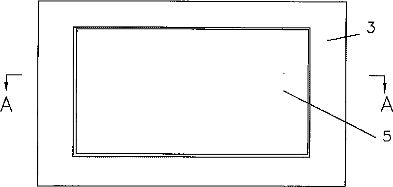
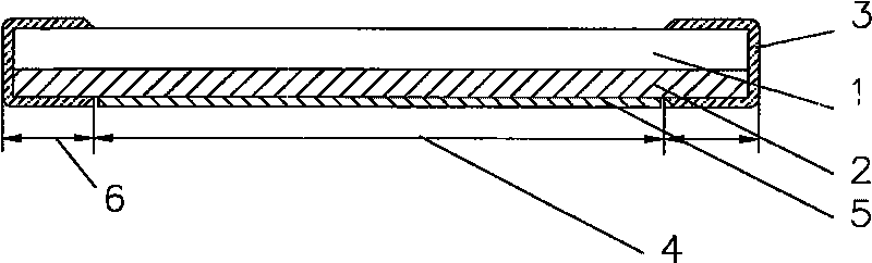
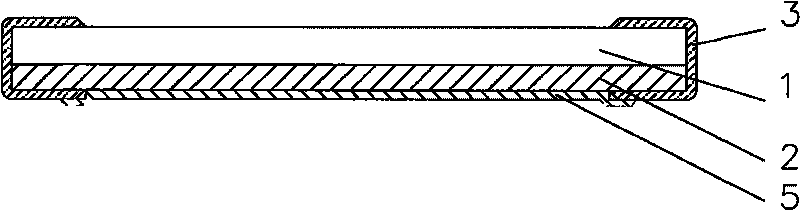
[0021] Figure 4 The structure diagram of the optical filter with two layers of conductive metal foil in the present embodiment 1 is given, see Figure 4 One side of the transparent substrate 1 (can be glass) is coated with a coating layer 2 for electromagnetic shielding (or is pasted with a copper mesh layer containing an adhesive layer pasted with the substrate for electromagnetic shielding), and the first layer of conductive metal foil 3 (Containing the conductive adhesive layer) A part of the conductive adhesive of the metal foil is used to paste the coating layer 2 (or copper mesh layer) along the edge of the substrate, and the other part is coated along the edge of the substrate to The other side of the substrate is also pasted with the substrate to form a coating on the edge of the substrate 1 and the coating layer 2, and on the coating layer 2 (or the copper mesh layer) is compounded with a layer of protective coating layer (or copper mesh layer). The resin layer 5 th...

Embodiment 2

[0023] Figure 5 Provided the figure of present embodiment 2, the optical filter sheet 8 that has two layers of conductive metal foils in the present embodiment is pasted together directly with the screen of display 9 with bonding agent 10, and this embodiment has thinned plasma display, Secondary reflections of the image are completely prevented.


PUM

PropertyMeasurementUnit
thicknessaaaaaaaaaa

Abstract

The invention relates to a light filter with two conductive metal foils. One surface of a transparent substrate is plated with a film coating used for electromagnetic shielding or adhered with a copper wire mesh used for electromagnetic shielding and is provided with two conductive metal foils as extraction electrodes, one part of a first conductive metal foil adheres the film coating or the copper wire mesh along at least two corresponding sides of periphery of the substrate through the conductive glue of the metal foil while the other part is cladded on the other surface of the substrate along the edge of the substrate and is adhered with the substrate, at least one resin layer preventing the film coating or copper wire mesh from being oxygenized and corroded is compounded on the film coating or copper wire mesh, the resin layer is also compounded with the first conductive metal foil adhered on the film coating or copper wire mesh, one part of a second conductive metal foil is adhered on the edge of the resin layer through conductive glue while the other part is cladded on the other surface of the substrate along the edge of the substrate and adhered with the first conductive metal foil adhered on the other surface of the substrate. The invention can improve production efficiency and reduce scrap rate and cost.

Description

Technical field: [0001] The present invention relates to a filter of a display device, in particular to a filter with anti-electromagnetic radiation and light filtering functions in a plasma display (PDP), and to a plasma display device using the filter. Background technique: [0002] At present, the plasma display must be equipped with an optical filter to prevent electromagnetic radiation and filter light between the display and the audience. The anti-electromagnetic radiation function of the optical filter is mainly to rely on a layer of copper mesh attached to the transparent substrate to cut off electromagnetic radiation waves or It is realized by plating with silver or silver alloy conductive film that cuts off the passage of electromagnetic radiation waves, but the cut-off of electromagnetic waves on the filter plane must rely on the conductive metal foil that is in good contact with the copper mesh or the conductive coating layer as the lead-out electrode to be connec...

Claims


Application Information

Patent Timeline
Patent Type & Authority Applications(China)
IPC IPC(8): G02B5/20H01J17/49
Inventor 甘国工
Owner 甘国工
Why Eureka
Try Eureka