Vacuum separation tank
A technology of vacuum separation and separator, which is applied in the direction of distillation separation, separation method, spray evaporation, etc., can solve the problems of poor atomization effect and poor oil degassing effect, and achieve high space utilization, large total area, easy disassembly convenient effect
- Summary
- Abstract
- Description
- Claims
- Application Information
AI Technical Summary
Problems solved by technology
Method used
Image
Examples
Embodiment 1
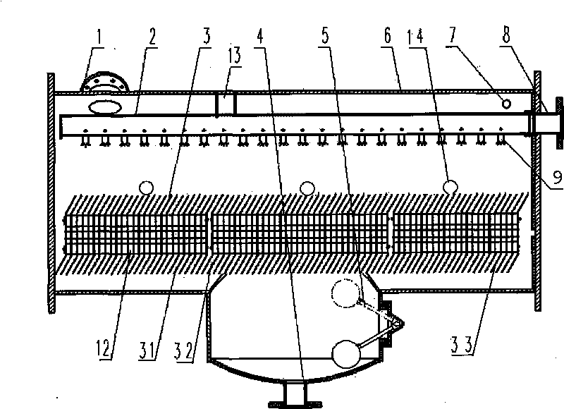
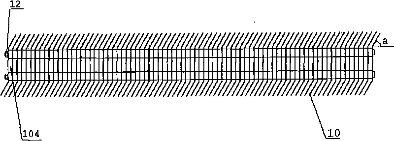
[0030] Such as figure 1 As shown, the vacuum separation tank of this embodiment includes a T-shaped housing 6, the upper part of the housing 6 is provided with a vacuum suction nozzle 1 and an oil inlet nozzle 8, and the bottom of the housing 6 is provided with an oil outlet nozzle. 4. A separator 3 and a fuel injector 2 connected to the oil inlet 8 are provided in the housing 6, and the separator 3 is arranged below the fuel injector 2. In this embodiment, the The fuel injector 2 includes a hollow stainless steel tube, and a rotating nozzle 9 arranged on the hollow stainless steel tube, and the rotating nozzle 9 can be arranged on the hollow stainless steel tube at different angles and at different intervals (such as figure 2shown). The top of the housing 6 is provided with a fixing device 13 for fixing the fuel injector 2 at a position corresponding to the middle section of the fuel injector 2. In this embodiment, the fixing device 13 is a sleeve set on the Retaining ring...
Embodiment 2
[0037] Such as Figure 6 As shown, the vacuum separation tank in this embodiment is basically the same as that in Embodiment 1, the difference is that in Embodiment 1, a vertical portion 104 is provided on the separation plate 10, while in this embodiment the The separating plate 10 is a plane without a vertical portion; in embodiment 1, the distance between the separator 3 and the injector 2 is 300mm, and in the present embodiment the distance is 200mm; in the embodiment 1, the spacing between the adjacent separation plates 10 of the separator 3 is 10mm, and in this embodiment the spacing is 5mm; The included angle a is 60 degrees, and in this embodiment is 30 degrees, and in this embodiment, the separator 3 includes eighty-five separation plates 10 .
Embodiment 3
[0039] The vacuum separation tank in this embodiment is basically the same as that in Embodiment 1, the difference is that in Embodiment 1, the distance between the separator 3 and the injector 2 is 300 mm, while in this embodiment This distance is 400mm; In embodiment 1, the spacing between the adjacent separating plates 10 of described separator 3 is 10mm, and in the present embodiment this spacing is 20mm; In embodiment 1, described separator The included angle a between the separation plates 10 of 3 and the horizontal direction is 60 degrees, and in this embodiment it is 80 degrees, and in this embodiment, the separator 3 includes fifteen separation plates 10 .
[0040] Such as Figure 7 As shown, in other embodiments, the separation plate 10 of the present invention can also be a curved surface, a folded surface or other shapes that can achieve the purpose of the present invention, which will not be listed one by one here, and the separation plate 10 is a curved surface ...
PUM
| Property | Measurement | Unit |
|---|---|---|
| angle | aaaaa | aaaaa |
Abstract
Description
Claims
Application Information
 - R&D
- Intellectual Property
- Life Sciences
- Materials
- Tech Scout
- Unparalleled Data Quality
- Higher Quality Content
- 60% Fewer Hallucinations
Browse by: Latest US Patents, China's latest patents, Technical Efficacy Thesaurus, Application Domain, Technology Topic, Popular Technical Reports.
© 2025 PatSnap. All rights reserved.Legal|Privacy policy|Modern Slavery Act Transparency Statement|Sitemap|About US| Contact US: help@patsnap.com


