Waste gas-dust separator for cement kiln head and waste gas-dust separation method thereof

A dust separator and dust separation technology, applied in separation methods, chemical instruments and methods, dispersed particle separation, etc., can solve the problems of increased investment in technical transformation, insufficient ventilation capacity of kiln head fans, increased power consumption, etc., so as to reduce wear and tear. , good social and economic effect, low resistance effect

Active Publication Date: 2010-06-16
ANHUI CONCH GRP +2
View PDF0 Cites 12 Cited by
  • Summary
  • Abstract
  • Description
  • Claims
  • Application Information

AI Technical Summary

Problems solved by technology

[0007] Some cement enterprises adopt the cyclone dust removal technology when designing the waste heat utilization boiler system at the kiln head, but the biggest problem exposed is that the original production line system resistance is increased by about 500Pa ~ 1000Pa, and the power consumption increases a lot; especially when it involves cement kilns When the waste heat utilization system of the old line is reconstructed, when the surplus capacity of the original exhaust fan at the kiln head is not very large, the ventilation capacity of the kiln head fan is insufficient and needs to be modified, increasing investment in technical transformation

Method used


Image

  • Waste gas-dust separator for cement kiln head and waste gas-dust separation method thereof
  • Waste gas-dust separator for cement kiln head and waste gas-dust separation method thereof
  • Waste gas-dust separator for cement kiln head and waste gas-dust separation method thereof

Examples


specific Embodiment approach

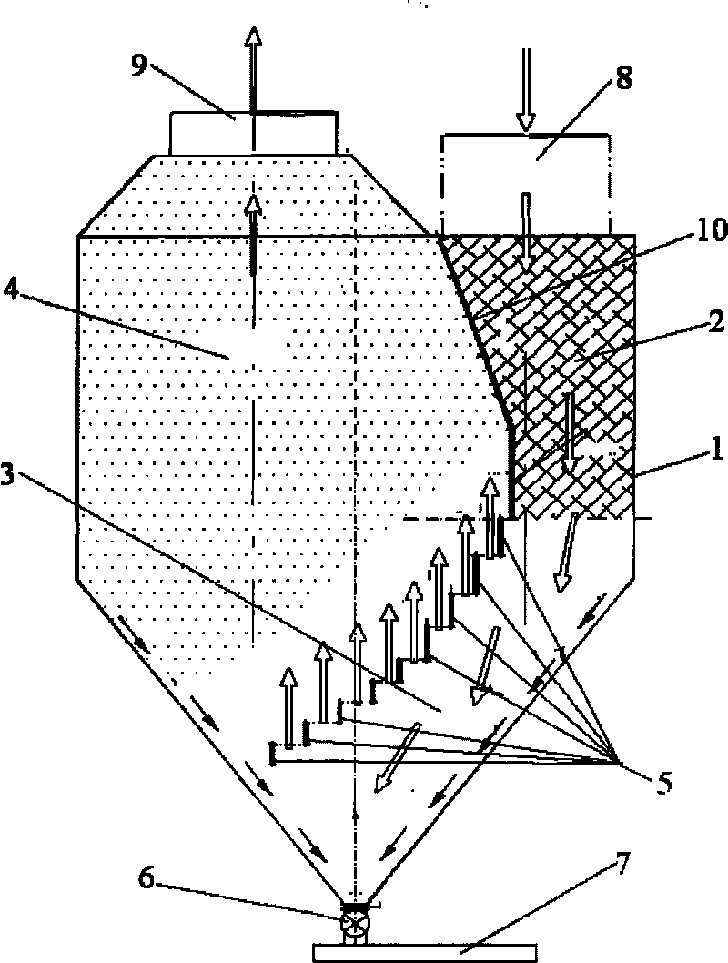
[0040] 1. The partition plate 10 of the present invention has a deflection in the direction of the air inlet 8 of the separator in the process of extending downward.

[0041] like figure 1 As shown, this structure greatly increases the volume of the outlet gravity settling chamber 4, further reduces the gas flow rate, and further separates the dust.

[0042] figure 1 The hollow arrow in the figure is the flow direction of the airflow, and the thin arrow is the flow direction of the separated dust.

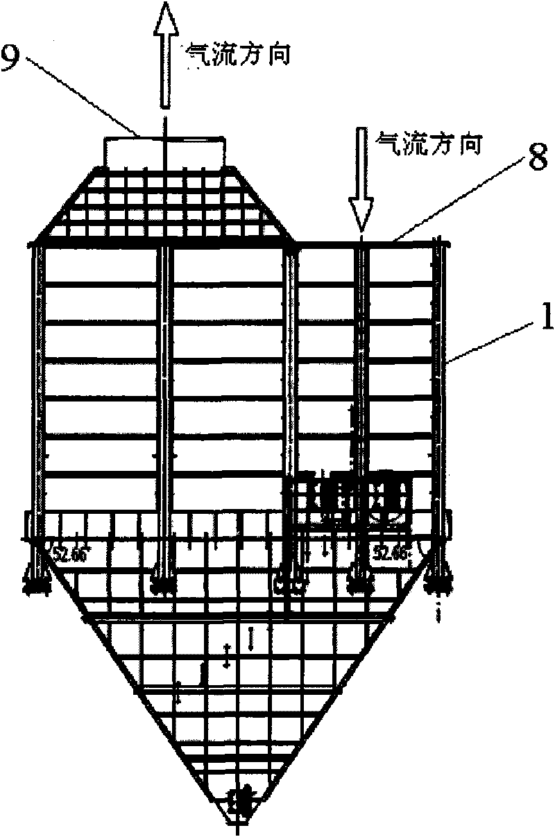
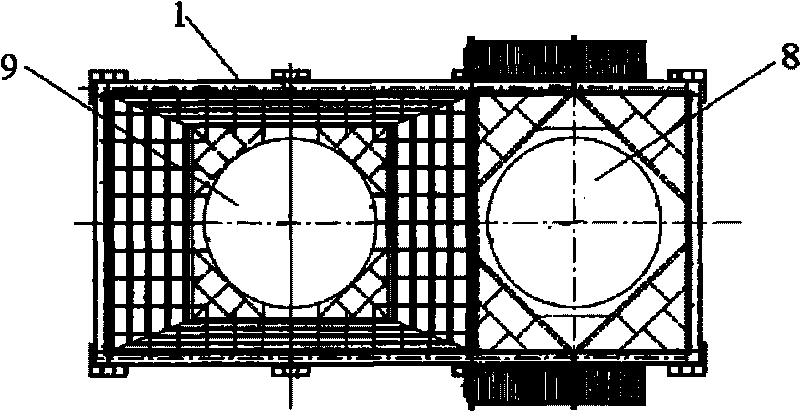
[0043] Two, such as figure 2 Shown: the separator air inlet 8 and the separator air outlet 9 of the present invention are circular holes, the horizontal cross-section of the cavity structure of the separator 1 is rectangular, and the area of ​​the circular holes is Smaller than the horizontal cross-sectional area of ​​the cavity structure of the separator 1 described above.

[0044] The purpose of this structure is also to greatly increase the volume of the entrance gravity se...


PUM

PropertyMeasurementUnit
particle diameteraaaaaaaaaa

Abstract

The invention discloses a waste gas-dust separator for a cement kiln head. The separator has a cavity structure, an air inlet and an air outlet of the separator are formed on a shell at the top end of the separator, a partition plate is arranged inside the separator, and the partition plate is arranged between the air inlet and the air outlet of the separator and is extended downwards to partition the cavity of the separator into an air inlet gravity settling chamber and an air outlet gravity settling chamber; and a through cavity is formed between the lower part of the partition plate and the shell of the separator so as to form a baffling gravity settling chamber. The invention also discloses a waste gas-dust separation method adopted by the separator. Due to the adoption of the technical scheme, the separation efficiency is improved to 70 percent compared with that of the traditional settling chamber, a rise of about 30 percent, so the separation efficiency is high; and the increased resistance of the system is low, an exhaust fan of the kiln head of the primary production line does not need to be reformed, the service life of a heat exchange surface of a waste heat utilization boiler reaches 2 years, and good social and economic benefits are obtained.

Description

technical field [0001] The invention belongs to the technical field of cement production, and relates to waste heat utilization technology of cement production. More specifically, the invention relates to a cement kiln head exhaust gas dust separator. In addition, the present invention also relates to the exhaust gas dust separation method of the separator. Background technique [0002] For a long time, it has been difficult to deal with the problem of dust wear caused by the use of exhaust gas from kiln heads in the cement industry for waste heat utilization. How to effectively solve the high-temperature dust wear of kiln head waste gas utilized by waste heat without increasing the system resistance of the original production line is an important issue faced by those skilled in the art. [0003] In the cement factory, the pure low-temperature waste heat utilization kiln head waste heat utilization boiler dust treatment has gone through the following two stages: [0004] 1...

Claims


Application Information

Patent Timeline
Patent Type & Authority Applications(China)
IPC IPC(8): B01D45/02B01D45/06F27D17/00
CPCY02P10/25
Inventor 郭文叁余彪张长乐夏贤清余生
Owner ANHUI CONCH GRP
Why Eureka
Try Eureka