Multi-functional auger bit

A kind of twist drill bit, multi-functional technology, applied in the direction of twist drill, etc., can solve the problems of wasting manpower, not being able to form large holes, labor-consuming and time-consuming, etc.

Inactive Publication Date: 2010-06-16
NANYANG POWER SUPPLY COMPANY OF STATE GRID HENAN ELECTRIC POWER
View PDF0 Cites 6 Cited by
  • Summary
  • Abstract
  • Description
  • Claims
  • Application Information

AI Technical Summary

Problems solved by technology

When the existing drill bit is processing a hole with a larger diameter, it must first use a small drill bit to punch out the positioning hole, and then replace the drill bits with different diameters in turn until a qualified hole is formed, and the chisel edge resista

Method used


Image

  • Multi-functional auger bit
  • Multi-functional auger bit
  • Multi-functional auger bit

Examples


Embodiment Construction

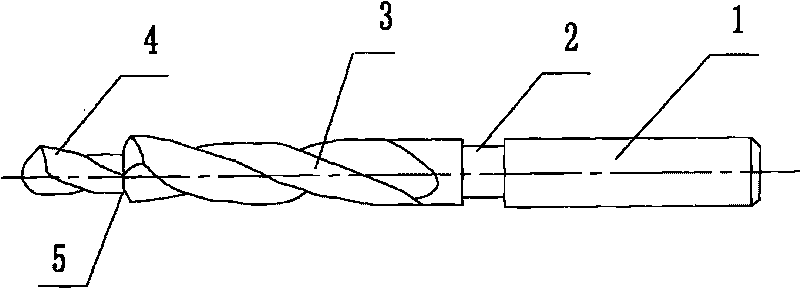
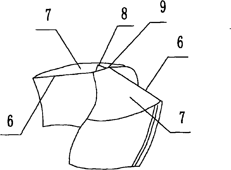
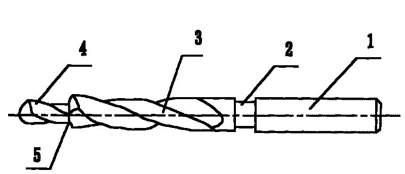
[0009] Such as figure 1 , 2 The multifunctional twist drill shown has a multifunctional twist drill with a shank 1, a neck 2 and a working part 3, the working part includes a guide part and a cutting part, and the cutting part is composed of a main cutting edge 5 and a flank, and the cutting The center of the part has a small-diameter twist drill 4 extending out. The small-diameter twist drill 4 has a guide part and a cutting part. The central position is provided with positioning tip 8.


PUM


Abstract

The invention discloses a multi-functional auger bit, comprising a handle portion, a neck portion and a working portion; wherein the working portion comprises a guide section and a cutting section and is characterized in that the cutting section is composed of a main blade and a rear tool face, the central part of the cutting section is provided with a small-diameter auger bit which extends to the outside, the small-diameter auger bit is provided with the guide section and the cutting section, the cutting section of the small-diameter auger bit is composed of the main blade, the rear tool face and a chisel edge, the central position of the chisel edge is provided with a positioning apex. Compared with the prior art, the multi-functional auger bit features self-positioning, easy operation and high processing efficiency, can form holes of different diameters at a time when in use and form larger holes at a time.

Description

technical field [0001] The invention belongs to the technical field of machining tools, and in particular relates to a multifunctional twist drill. Background technique [0002] The twist drill bit is a processing tool for processing holes. The existing twist drill can only form one round hole with the same diameter at a time, and if two holes with different diameters (such as countersink holes) are to be formed on the workpiece before processing, it is necessary to To replace the drill bit, first drill a smaller hole with a small drill bit, and then expand the drill with a large drill bit to process the required countersink hole. In the middle, the drill bit needs to be replaced, which wastes manpower, material resources, labor and time. The twist drill has a chisel edge, a main cutting edge and a flank. Due to the existence of the chisel edge, the twist drill cannot be positioned when drilling the workpiece. The drill is easy to swing at the beginning of cutting, which mak...

Claims


Application Information

Patent Timeline
IPC IPC(8): B23B51/02
Inventor 詹泽华詹总徐伟李望北刘富军李吉浩杜明哲詹元华徐博
Owner NANYANG POWER SUPPLY COMPANY OF STATE GRID HENAN ELECTRIC POWER
Why Eureka
Try Eureka