Convenient method for directionally cutting any crystal face of crystal

A technology for cutting crystals and crystal planes, applied in stone processing tools, manufacturing tools, stone processing equipment, etc., can solve the problems of wasting crystals and cumbersome work, and achieve the effects of saving crystals, wide application and high accuracy

Active Publication Date: 2010-06-16
IMDETEK
View PDF1 Cites 19 Cited by
  • Summary
  • Abstract
  • Description
  • Claims
  • Application Information

AI Technical Summary

Problems solved by technology

[0005] In order to overcome the disadvantages of tedious work and waste of crystals when the existing directional cutting technology cuts any crystal face directionally, the present invention provides a simple method for directional cutting any crystal face of the crystal, using electron backscatter diffraction technology to Combining the instrument with the traditional crystal mater...

Method used


Image

  • Convenient method for directionally cutting any crystal face of crystal
  • Convenient method for directionally cutting any crystal face of crystal
  • Convenient method for directionally cutting any crystal face of crystal

Examples


Embodiment 1

[0022] Example 1: Requirements in Hg 3 In 2 Te 6 A wafer with a (111) crystal plane cut out of the crystal, where Hg 3 In 2 Te 6 The theoretical value of 2θ corresponding to the (111) plane is 24.46°.

[0023] The steps for directional cutting are as follows:

[0024] (a) Cut out any plane as a reference plane.

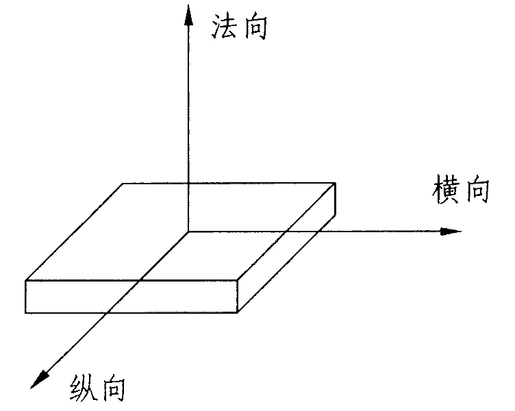
[0025] First stick the crystal on the cutting machine table with an adhesive, and then cut a wafer with uniform thickness from the edge of the crystal perpendicular to the table. The crystal plane close to the crystal on the wafer is used as a reference plane, and the reference plane is perpendicular to The downward direction of the pallet is regarded as the vertical direction, and the direction parallel to the right of the pallet is regarded as the horizontal direction. The vertical, horizontal and normal directions of the reference surface conform to the right-hand rule of the coordinate system, and then the reference surface is ground and polished until the s...

Embodiment 2

[0037] Embodiment 2: It is required to cut a wafer with (158) crystal plane on the germanium crystal, and the (158) crystal plane is the extinction surface of the germanium crystal.

[0038] The steps for directional cutting are as follows:

[0039] (1) Cut out any plane as a reference plane.

[0040] First stick the crystal on the cutting machine support with adhesive, and then cut out a wafer with uniform thickness from the edge of the crystal perpendicular to the support. The crystal plane close to the crystal on the wafer is used as the reference plane, and the reference plane is perpendicular to the support. The downward direction of the platform is regarded as the longitudinal direction, and the direction parallel to the right of the support platform is regarded as the transverse direction. The longitudinal, transverse and normal directions of the reference surface conform to the right-hand rule of the coordinate system, and then the reference surface is ground and polis...


PUM


Abstract

The invention discloses a convenient method for directionally cutting any crystal face of crystal, belonging to the technical field of crystal material cutting processing. The method is implemented by cutting out a plane arbitrarily to be as the reference plane, then determining longitudinal, transverse and normal indexes of the reference plane by using electron backscattered diffraction (EBSD) technology, then calculating the needed included angle between the reference plane and any crystal face, and finally regulating the crystal cutting direction to obtain the crystal face satisfying requirements by once cutting processing. With the EBSD technology adopted, the EBSD instrument and the traditional crystal material cutting device are combined, thus the crystal of any crystal system can be cut out any crystal face in directional way, namely, the needed crystal face is a high index diffraction face or an extinction face, the invention is especially suitable to the crystal with unknown reference plane orientation and larger crystal orientation deviation, and the bearing accuracy is high, the operation is simple and convenient and the crystal consumption is reduced.

Description

technical field [0001] The invention relates to a method for directionally cutting crystals, in particular to a simple method for directionally cutting any crystal face of the crystal; it belongs to the technical field of crystal material cutting and processing. Background technique [0002] Because single crystals have anisotropic properties, the influence of crystal orientation needs to be considered in aspects such as single crystal manufacturing, epitaxial growth, device fabrication, and die scribing. In practical applications, depending on the purpose of use, single crystals with different orientations are required, which requires us to cut the crystals with different orientations. [0003] Document 1 "Zhao Zhengxu, Directional Cutting of Semiconductor Crystals, Science Press, 1979" discloses three main directional cutting methods: cleavage method, optical image method, X-ray method, wherein X-ray method is divided into Laue photography method and X-ray orientation met...

Claims


Application Information

Patent Timeline
IPC IPC(8): B28D1/22
Inventor 介万奇傅莉罗林王新鹏王涛
Owner IMDETEK
Why Eureka
Try Eureka