Spool

A technology inside the bobbin and tube wall, which is applied in the field of textile devices, can solve the problems of easy wear and tear, waste of energy, and influence on bobbin forming, etc., and achieve the effect of firm packaging, long life and simple structure

Inactive Publication Date: 2010-06-16
TIANJIN POLYTECHNIC UNIV
View PDF2 Cites 5 Cited by
  • Summary
  • Abstract
  • Description
  • Claims
  • Application Information

AI Technical Summary

Problems solved by technology

But this method also has some problems: First, the electronic label is directly attached to the bobbin wall, whether it is pasted on the inside or the outside, and the obtained bobbin is only suitable for static, low speed or low rotational speed on the bobbin. identification, but cannot adapt to the requirements of high-speed spinning, that is, it cannot adapt to the requirements of radio frequency reading and writing of the high-speed rotating bobbin in the spinning process, so the actual use of the bobbin obtained by this method is greatly limited; secondly, if the electronic The label is pasted on the outside of the bobbin. Since the electronic label itself has a certain thickness (generally 0.8mm), plus the thickness of the epoxy resin and packaging material pasted, it will affect the shape and structure of the bobbin, and then affect the shaping of the bobbin. , which is contrary to the original intention of installing the electronic label; and if the electronic label is pasted on the inner side of the bobbin, it is difficult to carry out the actual pasting operation; again, after the bobbin is pasted with the electronic label, the bobbin where the electronic label is pasted will directly increase , the local shape is convex, easy to wear and damage during use, reduce the service life of the electronic label bobbin, or lose the function of the electronic label; finally, due to the use of epoxy resin to encapsulate and paste the electronic label on the bobbin, it needs to be dried Therefore, this pasting method has a complex technological process, consumes time, wastes energy, and also has a certain degree of pollution.

Method used


Image

  • Spool
  • Spool
  • Spool

Examples


Embodiment 1

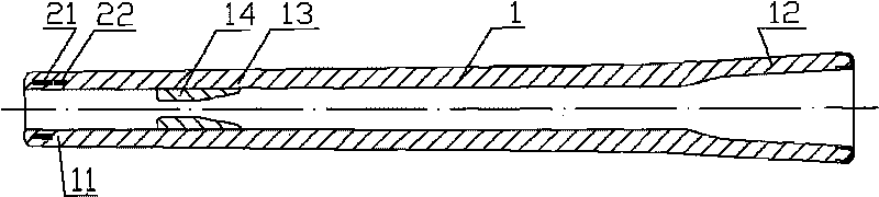
[0028] The coil 21 is integrated in the spun bobbin at the bobbin head end 11 (see figure 1 ).

[0029] The coil 21 is designed as an annular flat coil with an inductance of 3.45mH, an outer diameter of 10mm, and an inner diameter of 8mm; The axes are coincident; the chip 22 is selected from the EM4100 chip that matches the coil 21, and the chip 22 is placed in the tube wall 1 below the coil 2 at the head end 11 of the bobbin. After being electrically connected with the coil 21, they are connected to the bobbin by injection molding. The raw materials are integrated into bobbins of the present invention.

[0030] The spinning test is carried out with the bobbin of this embodiment. When the spinning spindle speed reaches 15,000 rpm, the radio frequency reader can still communicate with the radio frequency transponder 2 (or bobbin) normally.

Embodiment 2

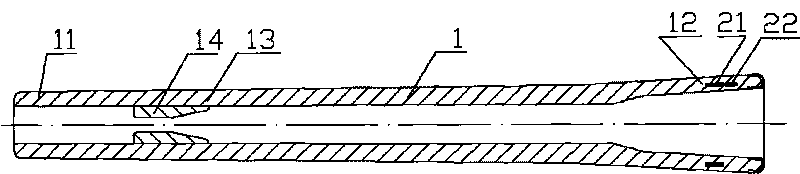
[0034]The coil 21 is integrated into the spun yarn bobbin at the bottom end 12 of the bobbin (see figure 2 ).

[0035] The packaging position of the radio frequency transponder 2 is at the bottom 12 of the spun bobbin, and the axis of the coil 21 coincides with the axis of the bobbin 1; the inner diameter of the coil 21 is 19 mm, the outer diameter is 23 mm, and the chip 22 is selected It is TK4100 chip. The rest are the same as embodiment 1.

Embodiment 3

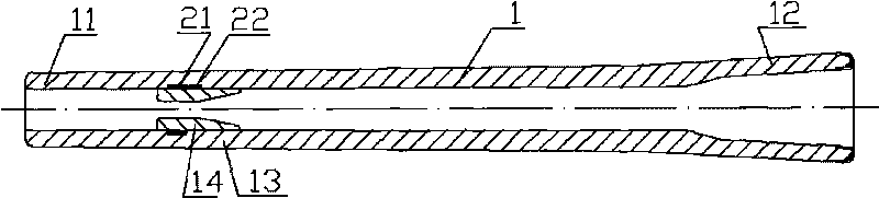
[0037] The coil 21 is integrated into the spun bobbin at the positioning ring 14 in the bobbin (see image 3 ).

[0038] The encapsulation position of the radio frequency transponder 2 is at the inner positioning ring 14 of the spun bobbin, and the axis of the coil 21 coincides with the axis of the bobbin 1; The radio frequency transponder chip 22 (produced in my country's Taiwan), the rest is the same as the embodiment 1.

[0039] The method of this embodiment is more convenient to embed and fix the radio frequency transponder 2 therein during the injection molding process of the bobbin.


PUM


Abstract

The invention discloses a spool which comprises a radio frequency transponder which is mainly composed of a minitype antenna coil and a radio frequency signal receiver chip, wherein the minitype antenna coil and the radio frequency signal receiver chip are matched. The spool is characterized in that the radio frequency transponder is integrated in the body of the spool or on the top surface, and the axis of the minitype antenna coil is coincident or parallel to the axis of the spool. The integrated radio frequency transponder can normally work when the spool is in static state, moves or rotates at low speed as well as at high speed.

Description

technical field [0001] The invention relates to a textile device, in particular a bobbin containing a radio frequency transponder. Background technique [0002] At present, textile enterprises are still unable to perform single-spindle inspection on the spinning frame. If a spindle of the spinning machine or a certain mechanism related to it fails, resulting in a problem with the spinning quality of the spindle, it is difficult to find out during the production process of the spun yarn, even if a tube of spun yarn is found through spot checks after spinning In the event of a quality problem, it is impossible to track down which spindle of the spinning frame the bobbin with the quality problem was spun, so the spinning quality problem caused by this single spindle or multiple spindles cannot be eliminated as soon as possible. The existing automatic winding machine can complete the inspection and statistics of the quality of each tube of spun yarn, but this quality inspection...

Claims


Application Information

Patent Timeline
Patent Type & Authority Applications(China)
IPC IPC(8): B65H75/18G06K19/07
Inventor 马崇启吕汉明
Owner TIANJIN POLYTECHNIC UNIV
Why Eureka
Try Eureka