High-speed electromagnetic valve driver circuit

A high-speed solenoid valve and drive circuit technology, applied in transformer/inductor circuits, valve details, valve devices, etc., can solve the problems of bootstrapping booster circuits not being able to bootstrap normally, increasing circuit complexity, and burning MOS tubes. To achieve the effect of increasing complexity, reducing reliability, improving efficiency and reliability

Active Publication Date: 2010-06-16
SICHUAN AEROSPACE FENGHUO SERVO CONTROL TECH CO LTD
View PDF2 Cites 57 Cited by
  • Summary
  • Abstract
  • Description
  • Claims
  • Application Information

AI Technical Summary

Problems solved by technology

The DC / DC expansion of its dual voltage undoubtedly increases the complexity of the circuit. The high and low power sources are switched through a high-end MOS tube respectively. Since the MOS tube is connected to the high-end, its drive circuit generally adopts a bootstrap boost method. When the circuit is switched, a high impact voltage is formed due to the continuous flow of the coil. This impact is likely to cause the bootstrap boost circuit to fail to bootstrap normally, thereby burning the MOS tube.

Method used


Image

  • High-speed electromagnetic valve driver circuit
  • High-speed electromagnetic valve driver circuit
  • High-speed electromagnetic valve driver circuit

Examples


Embodiment Construction

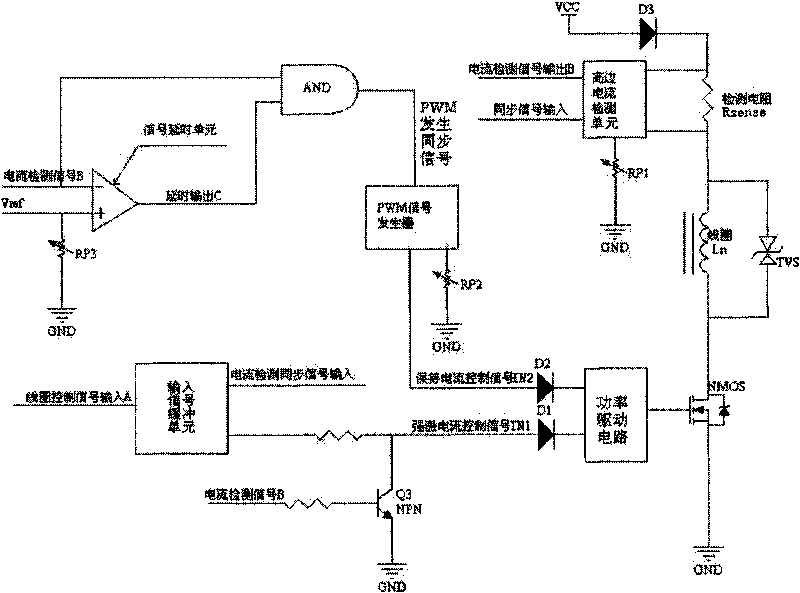
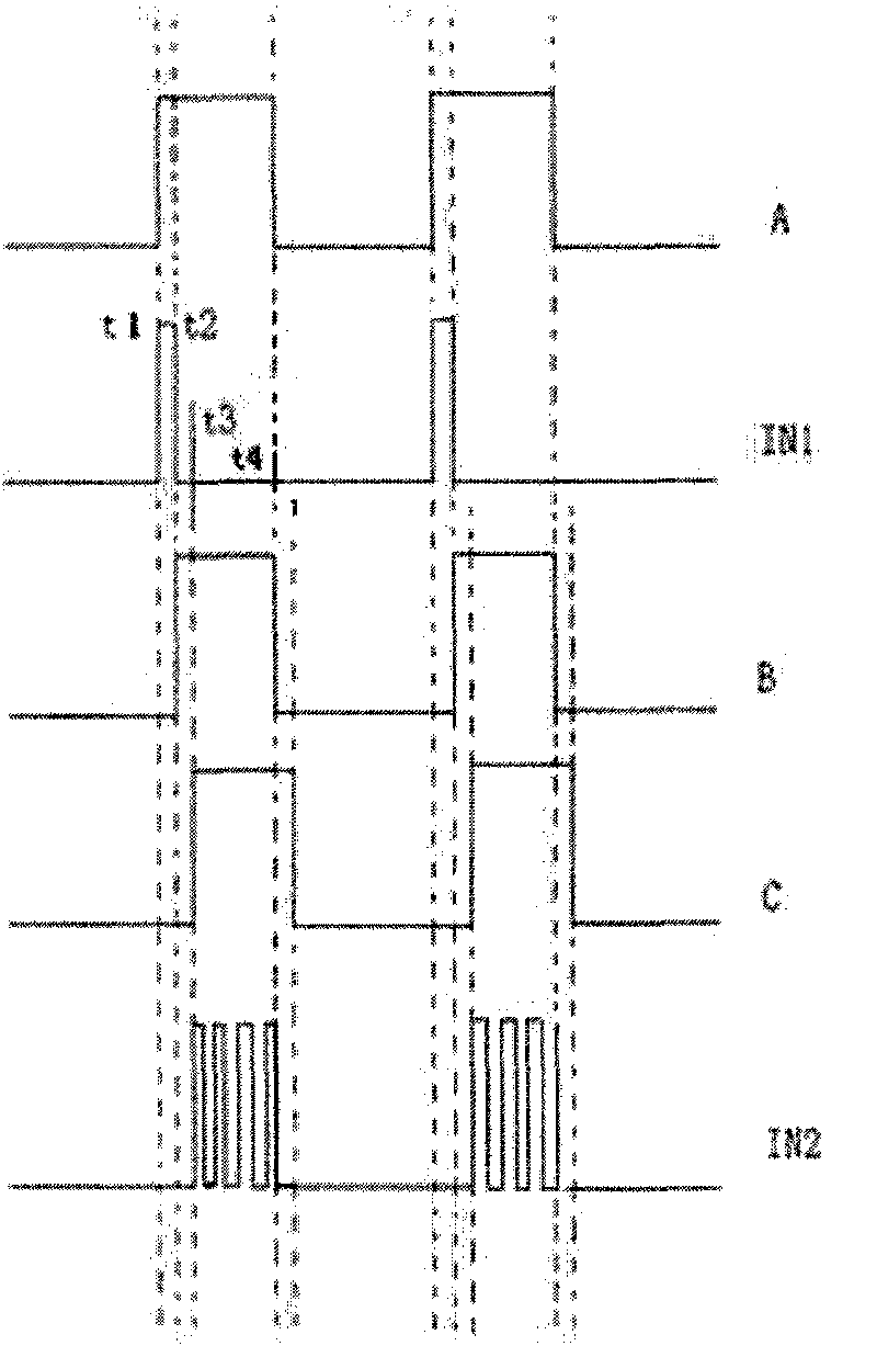
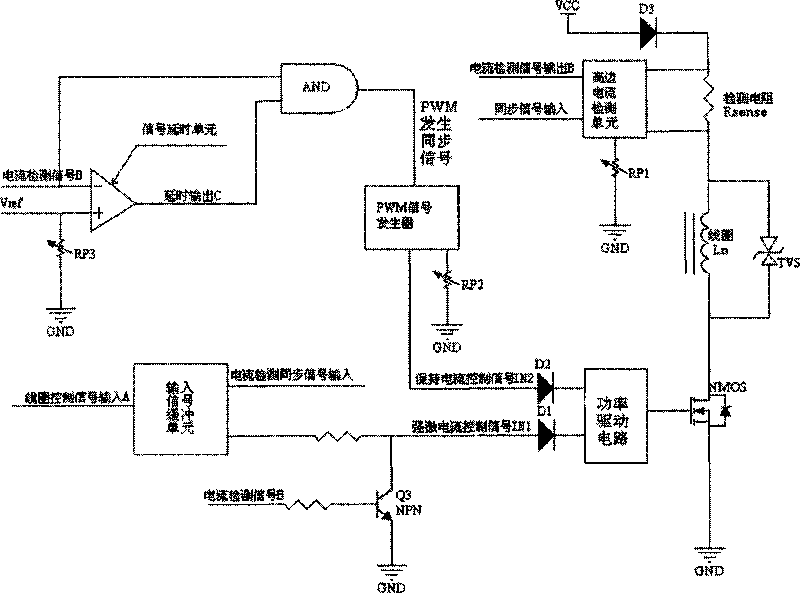
[0018] This circuit is mainly a high-speed solenoid valve drive circuit (this drive circuit can be used as a supporting drive circuit for the valve in the application number 200910090745.0 "Electromagnet and Switch Valve Using the Electromagnet"). According to the working principle, the solenoid valve core can be used Spring return can also use dual coils to push and pull the spool. Since the valve is a high-speed solenoid valve, its opening and closing time reach 1ms respectively, so its current response characteristics determine that its driving circuit should meet the following basic requirements. 1. The energy-intensive power before the solenoid valve is opened should inject energy into the solenoid valve at the highest possible rate to ensure that the solenoid control valve generates a sufficient electromagnetic force during the opening process and shorten the opening response time; 2. The solenoid valve is opened Finally, because the working air gap is small and the relu...


PUM


Abstract

The invention relates to a high-speed electromagnetic valve driver circuit. An input signal buffer unit mainly performs buffering shaping on an input signal from an external central control unit and improves the antijamming capacity thereof; a high side current detection unit realizes current detection by detecting differential voltage of one resistor in a load branch circuit; a PWM signal generator mainly generates a PWM wave with fixed frequency, the current is controlled and kept by regulating the duty cycle of the waveform; a power drive unit mainly supplies enough power drive for a power NMOS tube so that the power NMOS tube can fully operate in a switch state and reduce switch loss and heating; a signal time delay unit outputs a time delay for a current detection signal; in the delay time, the power NMOS tube is cut off, so that a coil can have afterflow; a logical gate circuit unit is a coincidence gate and generates a synchronizing signal required by the PWM signal generator after performing phasing on the current detection signal and a time delay signal thereof.

Description

technical field [0001] The invention relates to a solenoid valve driving circuit, which is especially suitable for driving a solenoid valve in an electronically controlled diesel engine fuel injection system, and belongs to the related technical field of solenoid valve driving. Background technique [0002] Conventional digital valves achieve micro control by increasing the response frequency. Although reducing the mass of the spool and the hydraulic force can increase the response frequency, the improvement of the response frequency of the switching valve mainly depends on increasing the force of the driver and reducing the response time. The driver of the high-speed switching valve is mainly a powerful electromagnet, and the general response time is milliseconds; high electromagnetic force requires more ampere-turns, which causes the solenoid valve to heat up and has a complex structure. In order to provide fast excitation current to the powerful electromagnet, its drivin...

Claims


Application Information

Patent Timeline
Patent Type & Authority Applications(China)
IPC IPC(8): F16K31/06H01F27/42F02D41/02
Inventor 李柏宏刘宇辉司国雷邓建辉唐兵
Owner SICHUAN AEROSPACE FENGHUO SERVO CONTROL TECH CO LTD
Why Eureka
Try Eureka