
CAN bus-based intelligent illumination control system

A technology of intelligent lighting control and CAN bus, applied in energy-saving control technology, lighting devices, light sources, etc., can solve problems such as increasing power load, pollution, and destroying ecological balance, and achieve energy saving, comfortable illumination environment, and improved reliability Effect

Inactive Publication Date: 2010-06-16
SHANGHAI ENJI ENERGY SAVING TECH +1
View PDF0 Cites 4 Cited by
  • Summary
  • Abstract
  • Description
  • Claims
  • Application Information

AI Technical Summary

Problems solved by technology

[0004] At present, my country's lighting electricity consumption accounts for 20-30% of building electricity consumption. At present, the dimming products or scene controllers produced by several electric companies focusing on intelligent lighting are basically open-loop control. When people enter the work area , will turn on the required light source according to the required work requirements, adjust the light output of the light source to achieve the desired illuminance level, but generally after adjusting a illuminance level, it will basically not change according to the indoor light intensity, When the light is good, it is easier to neglect to adjust the output of the light source, which will not only create a good and comfortable working environment, but also cause unnecessary energy waste and economic loss.
In addition, the electricity load has been increased, and while additional power investment has been increased, it has also caused a lot of pollution. According to expert calculations, every 10 billion kilowatts produced requires 5 million tons of coal and 54,000 tons of smoke and dust emissions. 78,000 tons, resulting in severe acid rain and destroying the ecological balance

Method used


Image

  • CAN bus-based intelligent illumination control system
  • CAN bus-based intelligent illumination control system

Examples


Embodiment Construction

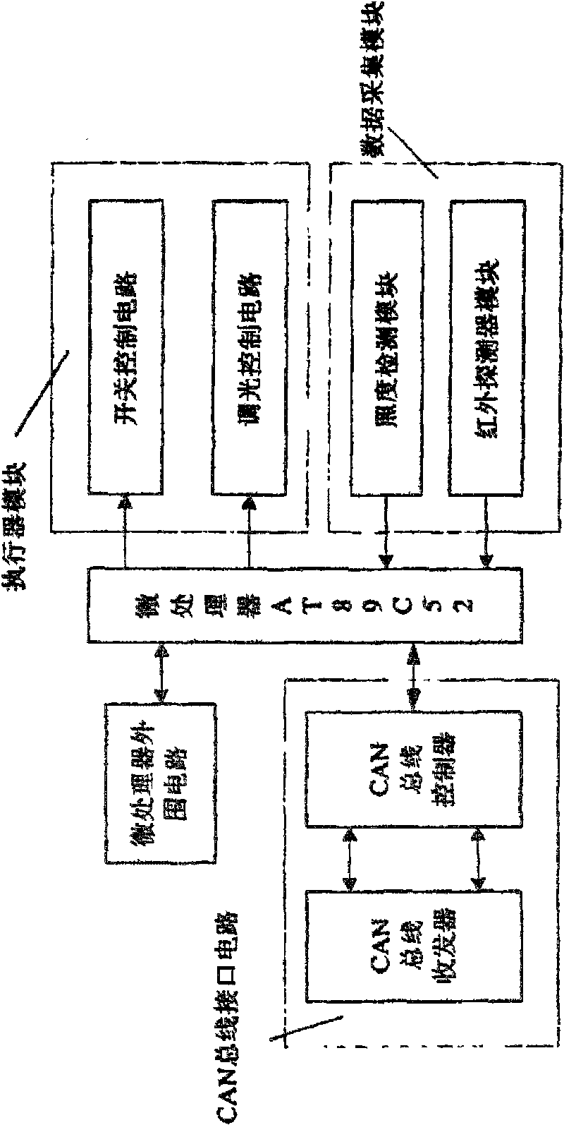
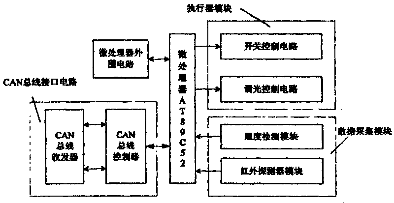
[0017] Such as figure 1 As shown, an intelligent lighting control system based on CAN bus, including CAN bus interface circuit, microprocessor, microprocessor peripheral circuit, execution module and data acquisition module, the CAN bus interface circuit, microprocessor peripheral circuit input The end is connected to the microprocessor, the output end of the microprocessor is connected to the execution module, the input end of the microprocessor is connected to the data acquisition module, and the output end of the CAN bus interface circuit is connected to the PC. The said connected microprocessor adopts 8-bit single-chip microcomputer AT89C52 manufactured by COMS technology as the core control chip. The CAN bus interface circuit includes a CAN bus controller and a CAN bus transceiver. The executive module is composed of a switch control circuit and a dimming control circuit. The data acquisition module is composed of an illumination detection module and an infrared detecto...


PUM


Abstract

The invention relates to the technical field of illumination device, in particular to a CAN bus-based intelligent illumination control system. The input ends of a CAN bus interface circuit and a microprocessor peripheral circuit are connected with a microprocessor; the output end of the microprocessor is connected with an execution module, and the input end of the microprocessor is connected with a data acquisition module; and the output end of the CAN bus interface circuit is connected with a PC machine. The system has the advantages that: the system is a distributed intelligent control system, overcomes the defects of excessive dependence on individual capability of a controller, relatively decentralized control and unavailable effective management, low timeliness and automatic degree and the like compared with the traditional illumination control system and simultaneously realizes dimming control which cannot be realized in an automatic illumination control mode.

Description

technical field [0001] The lighting equipment technical field of the present invention is specifically an intelligent lighting control system based on CAN bus. Background technique [0002] As early as the early 1990s, the international community put forward the imagery of "green lighting" for lighting systems that save electric energy and protect the environment. In the late 1980s, some developed countries such as the United States, Japan, the United Kingdom, and the Netherlands took the lead in promoting "green lighting". [0003] In October 1996, led by the State Economic and Trade Commission, the State Planning Commission, the Ministry of Science and Technology, the Ministry of Construction, the Ministry of Information Industry, the Ministry of Agriculture, the State Bureau of Quality and Technical Supervision, the State Administration of Domestic Trade, the State Power Corporation, the Chinese Academy of Sciences, China Energy Conservation Investment Corporation, etc. ...

Claims


Application Information

Patent Timeline
IPC IPC(8): H05B37/02
CPCY02B20/48Y02B20/40
Inventor 吴迪王帅水名岳周博楚舒宇
Owner SHANGHAI ENJI ENERGY SAVING TECH
Learn More